
If you are fitting out a factory or warehouse in Bengaluru or elsewhere in Karnataka, the fire pump is the machine that makes the hydrant and sprinkler systems work. A dedicated tank and a ring main will not help if the pumps cannot deliver the required flow and pressure when a fire starts, or during a power cut.
This guide is a buyer’s view of the fire pump set itself: the electric, diesel and jockey pumps, what the National Building Code of India 2016 and IS 12469 require, how to read a pump curve, how the fire pump room should be arranged, and the questions to ask before you award the work. It is general guidance, not a design. Your fire consultant and the Karnataka State Fire and Emergency Services decide what applies to your site.
For the hydrant network, water storage and yard hydrants that these pumps serve, see our guide to a fire hydrant system for factories and warehouses in Karnataka.
What a fire pump set includes
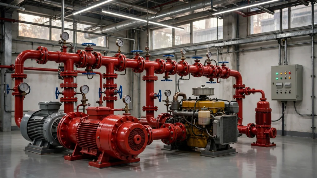
A typical industrial fire pump room has three kinds of pump, working as one set:
- One or more electric main fire pumps, which provide the design flow and pressure for hydrants and, where the scheme requires it, sprinklers.
- A diesel engine-driven standby pump of the same capacity, so the system can still run during a power failure. Where the approved scheme has two or more main pumps, the number of standby pumps follows the fire scheme (the hydrant code, IS 13039, sets this as half the number of main pumps).
- A jockey pump (sometimes called a booster or make-up pump), which keeps the mains pressurised by making up small leaks and thermal changes, so the main fire pumps do not start for a minor pressure drop.
NBC 2016, Part 4, Table 7 describes typical sets in its notes and in Figures 11 and 12: one electric and one diesel pump of equal capacity, plus one electric jockey pump of 180 litre/min; or two electric pumps and one diesel standby of equal capacity, plus two electric jockey pumps of 180 litre/min. Those notes also give example main-pump capacities of 1,620, 2,280 and 2,850 litre/min. They are starting points for the occupancies in Table 7, not a substitute for a calculated scheme.
The pumps must be used only for fire fighting, not for process or domestic water.
Which standards apply
Three documents come up on almost every industrial fire pump project in India:
National Building Code of India 2016, Part 4 (Fire and Life Safety). Table 7 lists minimum fire-fighting installations by occupancy, including pump capacity. Clause 5.1.2.2 sets out how the firefighting pump house is to be arranged. Figures 11 and 12 show typical pumping arrangements.
IS 12469:2019, Specification of Pumps for Stationary Fire Fighting Installations (First Revision). This is the Bureau of Indian Standards specification for the centrifugal fire pump itself: types, construction, the shape of the performance curve, factory tests, drive rating and nameplate data. BIS still lists this edition as active, with no amendments, as of 18 Nov 2026.
IS 13039:2014, External Hydrant Systems: Provision and Maintenance. This code covers the hydrant system that the pumps serve, including standby-pump provision, jockey-pump sizing, positive suction and routine running of the diesel engine. We walk through those hydrant-system rules in the hydrant guide.
In Karnataka, the fire-fighting scheme, including the pumps, is reviewed by the Karnataka State Fire and Emergency Services as part of the Fire NOC, and the installed work is inspected before clearance. We explain the stages in our article on Karnataka Fire NOC rules. Confirm the current documents and process with KSFES for your project.
How the fire pump capacity is decided
Do not start with a catalogue pump and work backwards. Capacity comes from the approved fire scheme.
For small-scale industrial buildings, NBC 2016 Table 7 gives minimum pump capacities, and Note 21 says pump capacity shall be based on the covered area of the building. Note 17 matters for most factories: the Group G (industrial) values in the table are for small-scale industry units. For other industries, the requirements are to be worked out from the relevant Indian Standards, in consultation with the local fire authority. For hydrant systems on medium and large industrial risks, that standard is typically IS 13039, which sizes pumping capacity by occupancy hazard class, not only by floor area.
Table 7 Note 22 adds a further hydrant-related rule: one set of pumps for each 100 hydrants or part thereof, with a maximum of two sets, and the delivery headers interconnected where more than one set is installed. Note 23 allows an additional diesel pump of the same capacity, and a doubling of the water-tank capacity required for one set, as an alternative to a second full set.
The selected pump must then meet that duty and the performance rules in IS 12469. IS 12469 lists standard manufacturer flow ratings in litre/min; those catalogue ratings are not the same list as the example capacities in the NBC Table 7 notes. Ask the vendor to show that the offered pump meets the approved scheme duty on its curve, not only that it is a “fire pump” in name.
What IS 12469 requires of the pump itself
IS 12469 is a product specification. The points below are the ones a buyer can actually check on a curve, a test certificate or a nameplate.
The curve must rise continuously. Head should increase as flow falls, so the pump has a stable operating characteristic.
Rated net pressure shall be 2.8 kg/cm² or higher.
At 150 percent of rated flow, the pump shall develop not less than 65 percent of its rated total head. This is the overload point you should see marked on the curve.
Shut-off head is limited. For end-suction, split-case, multistage and inline pumps, shut-off head shall not exceed 120 percent of rated head. For vertical turbine pumps, the maximum net pressure shall not exceed 140 percent of rated head. A steep shut-off can over-pressure the mains and fittings.
Power against flow shall be of the non-overloading type, so the driver is not asked for steadily more power as flow increases through the operating range.
Each pump is factory-tested. IS 12469 requires a hydraulic performance test (head at shut-off, at rated capacity, at 150 percent of rated capacity, and at selected points in between) and a production hydrostatic test of not less than 5 minutes at not less than 1.5 times the maximum working pressure, and in no case less than 17.2 kg/cm², with no rupture or leakage through the castings. Ask for the curve and the hydrostatic record with the pump’s serial number.
The nameplate must be of corrosion-resistant metal, visible after installation, and must include the manufacturer’s mark, rated capacity and head, rated speed, model, serial number, net head at 150 percent of rated capacity, number of stages, maximum power required at rated speed at any discharge condition, impeller diameter, and a rotation arrow.
Pumps conforming to the standard may also carry the BIS Standard Mark. That mark is not described in the standard as compulsory; if it matters for your specification or insurer, ask whether the offered pump carries it and for the test certificates that go with it.
Choosing the pump type
IS 12469 covers centrifugal fire pumps of several constructions. The common choices on industrial sites are:
- End-suction pumps — a horizontal pump with the suction nozzle opposite the stuffing-box side of the casing. Widely used for smaller duties. The standard says they should be used on a static suction lift only if a special provision for automatic priming is available.
- Split-case pumps — a horizontal pump whose casing is split along the shaft axis, which makes the rotating element easier to service. The same caution applies to suction lift: only with a separate priming source.
- Vertical turbine pumps — used where the water level is below the pump floor, for example when drawing from a deep underground tank, with the bowls in the water. Ratings, materials and tests must still conform to IS 12469.
- Multistage and inline pumps — used where the required head or the pipe arrangement makes them the better fit, including some taller buildings.
NBC 2016 is stricter than a “priming allowed” note. Clause 5.1.2.1 sizes the effective capacity of the fire reservoir above the top of the pump casing — that is, flooded suction. Clause 5.1.2.2(g) states that a negative suction arrangement and submersible pumps shall not be allowed. In practice, the pump should be installed so that it is flooded, not left to lift water.
Each pump should also be supplied with the fittings IS 12469 requires: an automatic air-release valve (not needed on self-venting pumps), a circulation relief valve (except on an engine-driven pump whose engine cooling water is taken from the pump discharge), and pressure gauges.
Sizing the electric motor and the diesel engine
A fire pump is of little use if the driver cannot cope with the full operating range.
For motor-driven pumps, IS 12469 requires that the motor shall not get overloaded anywhere between zero capacity and 150 percent of rated discharge. That is why the power curve must be non-overloading, and why you should see the maximum power, not only the power at rated duty, on the nameplate and in the motor selection.
For diesel engine-driven pumps, the standard requires a margin after correction for altitude and ambient temperature. The bare engine power rating shall be the higher of:
- 20 percent in excess of the maximum power required to drive the pump at its rated capacity, or
- the power required to drive the pump at 150 percent of its rated capacity.
Ask for the derating calculation for the actual site, not only a generic engine model number.
NBC 2016, clause 5.1.2.2, also requires a separate emergency charger for the diesel engine battery and an insulated exhaust taken to a safe location at ground level, allowing for back pressure. Those points are easy to miss on a crowded layout; they are listed with the other pump-room rules below.
IS 13039 calls for the diesel engine to be run for at least 5 minutes each day. Build that test into the handover training and the site’s routine, not only into the contractor’s commissioning week.
The fire pump room: NBC 2016 rules
The room is part of the fire system, not leftover space beside the tank. NBC 2016, Part 4, clause 5.1.2.2, requires the following:
- It is preferable to install the pump house at ground level, directly accessible from the surrounding ground.
- It shall not be installed lower than the second basement. If it is in a basement, a staircase with direct access from the ground is required, or an enclosed passageway with a 120-minute fire rating. Access shall not have to pass through other occupancies in the basement.
- The pump house shall be separated by fire walls all around, and the doors shall be 120-minute fire doors.
- It shall be well ventilated, and water stagnation shall be avoided.
- No other utility equipment shall be installed inside the fire pump room.
- Flexible couplings, bellows and similar insertions in the suction and delivery piping shall be suitably planned and installed.
- The room shall be large enough for all the pumps and their accessories, including pressure-reducing valves, the sprinkler installation control valve, other valves, the diesel tank and the electrical panel.
- Fire pumps shall be provided with a soft starter or a variable frequency drive starter.
Clause 5.1.3 adds that sprinkler installation control valves shall be installed inside the fire pump room. For industrial buildings, those valves may be installed outside the building, and the authorities shall be consulted where that is not possible inside.
These rules decide the civil layout as much as they decide the mechanical package. If the pump room is planned after the building is frozen, it is often too small, in the wrong basement, or shared with other utilities.
Controllers, starting sequence and the jockey pump
The set is only as reliable as the way it starts.
The jockey pump holds system pressure. IS 13039 generally sizes it at 3 to 5 percent of installed pumping capacity, with a minimum of 10.8 m³/h — which is 180 litre/min, the same jockey capacity named in the NBC Table 7 notes. If the jockey is undersized, or if the mains leak more than it can make up, the main fire pumps will cycle on small pressure drops. That wears the starters and leaves everyone unsure whether a start is a real demand.
Automatic starting, with a planned sequence so that pumps start in order rather than all at once, and an audible alarm, is part of a normal industrial scheme (see the hydrant guide for the IS 13039 wording). Pressure switches, the controller and the wiring between them should be in the scope, not assumed.
NBC 2016 also requires fire pumps to have a soft starter or a variable frequency drive starter. Whatever is offered, the controller still has to start the pump automatically under fire-demand conditions. Ask the vendor to show how the approved starting method is achieved, and to include it in the commissioning tests.
Testing, documents and handover
Before you accept the pump room, you should have more than a running demonstration.
- Factory performance curve and hydrostatic test record, tagged to the serial number on the nameplate.
- Confirmation that the installed impeller diameter and speed match the curve you were given.
- A site flow test against the approved duty, not only a shut-off pressure reading.
- Settings and a functional test of the jockey pump, the main electric pump, the diesel pump (including a start on simulated power failure), the alarms and the sequential start.
- As-built drawings of the room, suction and delivery, fuel and exhaust, and the controller wiring.
- Fuel, battery and cooling arrangements for the diesel set, and a demonstrated daily test-run procedure.
- Training for the people who will run the pumps after handover.
Our MEP testing, commissioning and handover checklist covers the documents to ask for. After handover, use those routines alongside our fire safety audit checklist for factories and warehouses in Bangalore.
Questions to ask before you award the work
- Which standard and hazard class (or Table 7 row) set the pump duty, and who agreed it with the fire authority?
- Can we see the hydraulic calculation and the pump curve at the approved duty, including the 150 percent flow / 65 percent head point and the shut-off head?
- Are the pumps to IS 12469, with factory performance and hydrostatic certificates against the nameplate serial numbers?
- Is suction flooded, in line with NBC 2016, with no negative suction or submersible fire pump?
- How have the electric motor and the diesel engine been sized against IS 12469, including altitude and temperature correction for the engine?
- Does the pump-room layout meet clause 5.1.2.2, including fire separation, access, ventilation, diesel exhaust, a separate battery charger, and no other utilities in the room?
- Who supplies the controllers, pressure switches and starting sequence, and how will they be tested?
- Who prepares the fire-scheme drawings for the Fire NOC, and who attends the KSFES inspection?
- What training and documents will we receive at handover?
Frequently asked questions
A typical set is one or more electric main fire pumps, a diesel standby pump of the same capacity, and a jockey pump to keep the mains pressurised. NBC 2016 Table 7 Notes 10, 11, 12 and 14, with Figures 11 and 12, describe these arrangements. The exact number and duty come from the approved fire scheme.
So the system can still run during a power failure. Where the main pumps are electric, IS 13039 requires a diesel standby pump. NBC 2016’s typical sets likewise include a diesel pump as standby.
It makes up small pressure losses so the main fire pumps are not started by minor leaks. IS 13039 generally sizes it at 3 to 5 percent of installed pumping capacity, with a minimum of 10.8 m³/h (180 litre/min). NBC 2016 Table 7 also uses a 180 litre/min electric jockey pump in its typical sets.
NBC 2016 does not allow a negative suction arrangement, or submersible pumps, in the firefighting pump house. The effective fire-water capacity is measured above the top of the pump casing (flooded suction). IS 12469 allows end-suction and split-case pumps on a static suction lift only with a special priming provision, but the Code rule for the room is flooded suction. Confirm the arrangement with your fire consultant and KSFES.
Under IS 12469:2019, the curve should be continuously rising, rated net pressure should be at least 2.8 kg/cm², the pump should still develop at least 65 percent of rated head at 150 percent of rated flow, shut-off head should stay within the limit for that pump type (120 percent of rated head for end-suction, split-case, multistage and inline pumps; 140 percent maximum net pressure for vertical turbine pumps), and the power curve should be non-overloading.
Often they are fed from the same pump room, and NBC 2016 shows combined wet-riser and sprinkler arrangements. Sprinkler installation control valves are to be installed inside the fire pump room, though for industrial buildings they may be placed outside with the authority’s agreement. Whether hydrants and sprinklers share a pump set, or need separate pumps, is decided in the approved fire scheme. For how sprinklers themselves work, see our guide to how fire sprinkler systems work.
The Karnataka State Fire and Emergency Services reviews the fire-fighting scheme, including the pumps, as part of the Fire NOC. After installation, the department inspects the as-built work before clearance. We explain the stages in our article on Karnataka Fire NOC rules. Confirm the current documents and process with KSFES for your project.
Talk to SRJ Group
Since 1985, SRJ Group has delivered piping and fire protection work for industrial clients. Our fire protection systems team designs, installs and commissions fire pump sets — electric, diesel and jockey pumps with automatic controllers — along with hydrant networks and related systems. If you are planning a fire pump room for a factory or warehouse in Karnataka, contact us with your drawings and we will review the scope with you.
Sources
- Bureau of Indian Standards, IS 12469:2019, Specification of Pumps for Stationary Fire Fighting Installations (First Revision). BIS e-Sale catalogue (Active, 0 amendments), checked 18 Nov 2026: https://standardsbis.bsbedge.com/BIS_SearchStandard.aspx?Standard_Number=IS+12469&id=3396
- Bureau of Indian Standards, National Building Code of India 2016 (SP 7:2016), Volume 1, Part 4 Fire and Life Safety, clauses 5.1.2.1, 5.1.2.2 and 5.1.3, Table 7 Notes 10–14, 17 and 21–23, and Figures 11–13. BIS National Building Code page: https://www.bis.gov.in/standards/national-building-code/
- A Table 7 extract is also published by Uttarakhand Fire and Emergency Services: https://ukfireservices.com/uttarakhand_fire/wp-content/uploads/2024/02/Table-7-NBC-2016-Volume-1-Part-4.pdf
- Bureau of Indian Standards, IS 13039:2014, External Hydrant Systems: Provision and Maintenance: Code of Practice (First Revision), reaffirmed 2019. Cited by name only: no stable official BIS catalogue page for this standard was loaded on 18 Nov 2026.
- The Hindu, “Now, apply for fire no-objection certificates online”, 29 July 2018: https://www.thehindu.com/news/cities/bangalore/now-apply-for-fire-no-objection-certificates-online/article24543674.ece
- SRJ Group, Karnataka Fire NOC rules: https://srjpipingindia.com/karnataka-fire-noc-rules-21m-height-clearance-certificate-rfo-powers/
- SRJ Group, Fire hydrant system for factories and warehouses in Karnataka: https://srjpipingindia.com/fire-hydrant-system-factory-warehouse-karnataka/