SRJ Piping India company logo – leaders in fire protection, industrial piping, and heavy structural fabrication solutions

Compressed Air Piping vs. Traditional Pneumatic Systems: Which One Is More Efficient?

Compressed Air Piping vs. Traditional Pneumatic Systems: Which One Is More Efficient?

Table of Contents

Pneumatic systems are vital in industrial automation, but historically suffered from inefficient, leak-prone piping. Modern compressed air piping, however, offers significant advancements beyond traditional methods, optimizing air distribution and energy utilization. 

This article will compare traditional and modern pneumatic piping, analyzing their impact on energy consumption, pressure drop, leakage, installation, maintenance, and total cost of ownership to determine which approach offers superior efficiency and performance for industrial applications.

Understanding Traditional Pneumatic Systems

Traditional pneumatic systems typically consist of several core components: a compressor to generate compressed air, air treatment equipment (filters, dryers, lubricators), a network of pipes to distribute the air, control valves, and actuators (cylinders, motors) to perform work. 

Illustration of an industrial compressed air and pneumatic system with tanks, gauges, piping, and bottling machinery.

How Traditional Pneumatics Work

At its heart, a pneumatic system utilizes compressed air as its working fluid. The compressor draws in ambient air, compresses it to a higher pressure, and stores it in a receiver tank. This pressurized air is distributed through a piping network to various use points. 

The traditional approach to the piping network often relied on readily available and seemingly robust materials like galvanized steel or black steel pipe. 

Strengths of Traditional Pneumatics

Despite their inefficiencies, traditional pneumatic systems gained popularity for valid reasons:

  • Simplicity: Compared to hydraulic systems, pneumatics are generally simpler in design and operation. Air is readily available, and the basic components are straightforward.
  • Robustness: Pneumatic components are often very durable and can withstand harsh industrial environments.
  • Safety: Air is non-flammable, reducing fire hazards compared to hydraulic fluid. Overload conditions typically result in the system stalling rather than causing damage, and they are generally cleaner than hydraulic systems (no oil leaks).
  • Force and Speed: Pneumatic cylinders can generate significant force, and actuators can operate at high speeds, making them suitable for rapid pick-and-place operations or clamping tasks.

Inherent Efficiency Challenges

While offering these advantages, the traditional approach to pneumatic systems, particularly concerning piping, introduced significant inefficiencies:

  • Pressure Drop: This is perhaps the most significant challenge. As air flows through pipes, friction with the pipe walls and turbulence caused by fittings, bends, and changes in pipe size lead to a loss of pressure. 
  • Leakage: Traditional piping materials and joining methods (threaded fittings, particularly) are highly susceptible to leaks. A seemingly small leak can add up to significant energy losses over time.
  • Control Losses: Inefficient control methods (e.g., using simple restrictors to control cylinder speed) can also waste compressed air, exhausting air that could have been used more effectively. 
  • Contamination Issues: Older piping materials like galvanized steel can corrode internally, leading to rust and scale buildup. This contamination restricts airflow, increases pressure drop, and damages downstream equipment, reducing efficiency and increasing maintenance needs.

These inherent challenges meant that a significant portion of the energy put into compressing air in traditional systems was lost before it could perform valuable work. The piping network, often an afterthought, was frequently the weakest link regarding efficiency.

Introducing Modern Compressed Air Piping Systems

Modern compressed air piping systems are designed with efficiency, performance, and total cost of ownership as primary considerations. They move away from the limitations of traditional materials and designs, embracing materials and methods specifically engineered for compressed air distribution.

Industrial compressed air piping system with labeled steel pipelines and directional flow indicators inside a manufacturing facility.

Beyond the Basics: The Role of the Piping Network

The piping network is no longer just a passive conduit in a modern system. It’s an active component critical to delivering compressed air at the required pressure and flow rate to every point of use with minimal loss. The design, materials, and installation quality of the piping directly impact the overall efficiency of the entire compressed air system. 

Modern Piping Materials and Their Advantages

The choice of piping material is fundamental to a modern compressed air system. Materials like galvanized and black steel, common in traditional setups, are now largely considered outdated for compressed air due to their propensity for corrosion, flow restriction, and leakage. Modern systems primarily utilize:

  • Aluminum: Lightweight, easy to install, corrosion-resistant, and offers smooth internal surfaces for minimal friction. 
  • Stainless Steel: Highly corrosion-resistant, making it ideal for food processing, pharmaceuticals, and other cleanroom or wash-down environments.
  • Copper: Corrosion-resistant and durable, often used in smaller systems or where specific jointing methods (soldering/brazing) are preferred. 
  • Plastic (e.g., PE-RT, Nylon): This material is suitable for specific low-pressure or smaller diameter applications, offering good corrosion resistance and ease of installation. 

Each material has its place, but systems designed for energy efficiency increasingly lean towards aluminum or stainless steel due to their combination of smooth bore, corrosion resistance, and modern joining technologies that minimize leak points.

Optimized Design Principles

Modern compressed air piping goes hand-in-hand with optimized system design. Key principles include:

  • Loop Systems: Designing the main distribution line as a loop ensures that air can reach any point of use from at least two directions. 
  • Proper Sizing: Undersized piping significantly increases air velocity and pressure drop, wasting energy. Oversized piping increases installation cost. 
  • Minimizing Bends and Fittings: Every bend, tee, or reducer introduces turbulence and pressure drop. When fittings are necessary, using full-bore, low-resistance types is crucial.
  • Strategic Location of Take-offs: Drops to points of use should ideally come off the top of the main header to prevent condensed moisture from flowing into downstream equipment.
  • Sectionalizing: Incorporating isolation valves allows system sections to be shut down for maintenance or modification without affecting the entire plant, improving flexibility and reducing downtime.

The Core of the Comparison: Efficiency Deep Dive

Comparing compressed air piping versus pneumatic systems, particularly in terms of efficiency, isn’t just about the air usage at the actuator. It’s about the energy required to deliver that air and the losses incurred. This is where the piping network’s impact becomes most apparent.

Energy Consumption: The Biggest Cost Driver

Compressed air is often referred to as the “fourth utility” in manufacturing, and it’s typically one of the most expensive forms of energy. Compressed air is energy-intensive, and approximately 80% of the total cost of ownership for a compressed air system is attributed to the electricity required to run the compressor. 

How Piping Impacts Compressor Load: The compressor maintains a required pressure level throughout the system. An inefficient piping system forces the compressor to consume more energy to deliver the same usable pressure and flow at the point of work.

Pressure Drop: The Silent Efficiency Killer: A pressure drop in the piping network means that the pressure generated at the compressor outlet is significantly higher than the pressure available at the point of use. For every 2 PSI of pressure drop, energy consumption is estimated to increase by approximately 1%. 

Measuring and Reducing Pressure Drop: Identifying and quantifying pressure drop is crucial.

Strategies to reduce pressure drop include:

    • Properly sizing pipes for the required flow and distance.
    • Using smooth-bore modern piping materials.
    • Minimizing the number of bends and fittings.
    • Using full-bore fittings.
    • Designing loop systems for better flow distribution.

Leakage: A Major Source of Wasted Energy

Leaks are endemic in many older or traditional compressed air systems. A single 1/8-inch leak can waste hundreds of dollars in electricity per year. The cumulative energy loss across an entire plant with multiple small leaks can be staggering. 

Why Leaks Happen in Traditional Systems: Threaded fittings, common in steel or iron piping, are notoriously difficult to seal perfectly and are prone to developing leaks over time due to vibration, temperature changes, or corrosion. 

Modern Piping’s Role in Leak Prevention: Modern piping systems, particularly aluminum and stainless steel, utilize precision-engineered connection methods like push-to-connect, compression fittings, or specialized clamps. 

Leak Detection and Management Strategies: Some leaks, even with the best piping, can occur over time. Modern systems facilitate easier leak detection (ultrasonic detectors are standard tools) and repair due to the accessibility and modularity of the components.

System Design and Control Efficiency

Beyond just delivering air with minimal pressure drop and leakage, the piping network influences the overall responsiveness and control of the pneumatic system. Pneumatic system design optimization considers the entire network.

Impact of Piping Layout on Responsiveness: Long, convoluted piping runs can introduce delays in air reaching the actuator, affecting system cycle times and overall responsiveness, particularly in high-speed automation. 

Centralized vs. Decentralized Systems: The piping network design is central to deciding between centralized and decentralized systems. A well-designed modern piping system can efficiently deliver air from a central compressor room to dispersed use points. 

Integration with Modern Control Methods: As pneumatic systems become more sophisticated with proportional valves and advanced control algorithms, the stability and consistency of the air supply delivered by the piping become even more critical for precise operation and energy efficiency.

Installation, Maintenance, and Total Cost of Ownership

While efficiency is a primary driver, the choice between modern compressed air piping and traditional methods also significantly impacts installation time, ongoing maintenance costs, and the total cost of ownership (TCO). A cost comparison of pneumatic vs. compressed air systems must consider these factors.

Installation Speed and Cost

This is a significant area where modern piping systems offer a distinct advantage.

Traditional Piping (Steel, Iron): Installation is labor-intensive. Cutting, threading, and joining metal pipes requires specialized tools and skilled labor. Sections are heavy and difficult to handle. Multiple threaded connections increase installation time and the potential for errors, leading to leaks. 

Modern Piping (Aluminum, Modular Systems): Installation is significantly faster and easier. Aluminum pipe is lightweight and easy to cut. Modular systems utilize quick-connect or simple clamp fittings that require minimal tools and labor. In-house maintenance teams can often install systems. 

Modern piping’s speed and ease of installation can offset a potentially higher material cost than traditional steel pipe, especially in large or complex installations.

Maintenance Requirements and Longevity

Ongoing maintenance is critical to a compressed air system’s long-term cost and reliability. Pneumatic system maintenance requirements vary depending on the piping.

Traditional Piping: Prone to internal corrosion, leading to scale and rust that contaminate the air and necessitate system flushing or component replacement. 

Modern Piping: Materials like aluminum and stainless steel are inherently corrosion-resistant, significantly reducing internal contamination and extending the life of downstream equipment. 

The lower maintenance burden and longer lifespan contribute significantly to the cost-effectiveness of modern piping systems in terms of their operational life. Material selection for compressed air systems is key here.

Total Cost of Ownership (TCO) Analysis

When evaluating compressed air piping vs pneumatic system approaches, it’s crucial to look beyond the initial purchase price and consider the total cost of ownership over the system’s lifecycle.

  • Initial Cost: Traditional steel piping often costs less per foot than modern materials like aluminum or stainless steel. 
  • Operating Cost: This is where modern piping systems shine. The reduced pressure drop and minimal leakage translate directly into lower compressor energy consumption. 
  • Maintenance Cost: Lower leak incidence, reduced contamination, and easier repair/modification contribute to lower maintenance costs for modern systems.
  • Downtime Cost: Easier maintenance and modifications mean less system downtime, a critical factor in manufacturing environments.

A comprehensive TCO analysis factoring in energy savings from reduced pressure drop and leaks, lower installation labor, reduced maintenance, and minimized downtime invariably favors modern compressed air piping systems for most industrial applications compared to traditional methods.

Real-World Applications and Case Studies

The theoretical advantages of modern compressed air piping translate into tangible benefits in various industrial settings. While detailed case studies might be proprietary, we can discuss the real-world efficiency gains pneumatic to compressed air systems see when upgrading their piping. 

Bridging Academic Findings to Industrial Practice

Research highlighted earlier, such as studies on pneumatic system optimization (like those from SpringerOpen and MDPI), often delve into the complex dynamics of airflow, pressure control, and energy loss within pneumatic circuits. 

These fundamental physics and research insights directly inform modern compressed air piping design principles, such as proper pipe sizing (to keep velocity low and minimize friction) and minimizing fittings and bends (to reduce turbulence). 

Therefore, choosing modern piping is not just about selecting a material; it’s about adopting a system designed based on sound engineering principles validated by research to maximize energy efficiency throughout the network.

Examples of Efficiency Gains

While specific numbers vary greatly depending on the original system’s condition, the plant size, and the application, upgrading or installing a modern compressed air piping system commonly results in:

  • Significant Energy Savings: After replacing old, leaky, and undersized piping with modern, optimized systems, reductions in energy consumption ranging from 10% to 30% or even more are frequently reported. 
  • Improved System Performance: Reduced pressure drop means tools and machinery operate at their intended pressure, leading to consistent performance, faster cycle times, and potentially fewer production issues related to inadequate air supply.
  • Lower Maintenance Costs: Less time spent chasing and fixing leaks, less need to replace air treatment components prematurely due to contamination from corroding pipes, and easier system modifications reduce ongoing labor and parts costs.
  • Reduced Downtime: A more reliable system with fewer leaks and easier maintenance/modification means less unplanned downtime for repairs or system changes.

Let’s consider a simplified case study:

Manufacturing Plant Upgrade

Situation: A medium-sized automotive components manufacturer relies heavily on pneumatic tools and automation. Their compressed air system uses aging galvanized steel piping installed piecemeal over decades, resulting in a significant pressure drop (15 PSI across the plant) and numerous audible leaks. The compressor runs almost constantly to maintain sufficient pressure.

Action: The plant upgrades the leading distribution network and drops using a modern, properly sized aluminum modular piping system, designed as a loop. Leaks are repaired during the upgrade.

Result: Pressure drop is reduced to less than 3 PSI. The compressor load decreases dramatically, allowing it to cycle less frequently or operate more efficiently. Compressed air energy bills drop by 25%. Tool performance improves, reducing scrap rates on specific operations. Maintenance time spent on leak repair is reduced by 80%. 

Conclusion

Modern compressed air piping significantly outperforms traditional pneumatic systems’ efficiency due to advanced materials (aluminum, stainless steel) and optimized designs. 

While initial installation may cost more, modern systems drastically reduce pressure drop and leaks, leading to lower energy consumption, maintenance, and downtime, ultimately resulting in a lower total cost of ownership. 

Investing in a modern, energy-efficient piping system is an economic necessity for industrial operations, maximizing productivity and minimizing waste. 

Consulting SRJ experts for optimal design and implementation is highly recommended.

Know about us more

  1. The Ultimate Guide to Industrial Piping Systems
    This blog provides a comprehensive overview of industrial piping systems, offering valuable context for understanding the efficiency of compressed air piping compared to traditional pneumatic systems.
  2. Key Benefits of Professional Piping Inspection Services
    This blog highlights the importance of regular inspections, which are crucial for maintaining the efficiency and reliability of compressed air piping systems.
  3. American Society of Mechanical Engineers (ASME) – B31.3 Process Piping
    ASME’s B31.3 standard provides guidelines for designing and maintaining piping systems, including those for compressed air, ensuring efficiency and safety.
  4. Compressed Air Challenge – Best Practices
    This resource offers best practices for optimizing compressed air systems, providing insights into improving efficiency in piping design and operation.


Optimizing Your Air Systems for Maximum Efficiency?

Let SRJ Piping India help you choose between compressed air piping and pneumatic systems for optimal performance and energy savings.

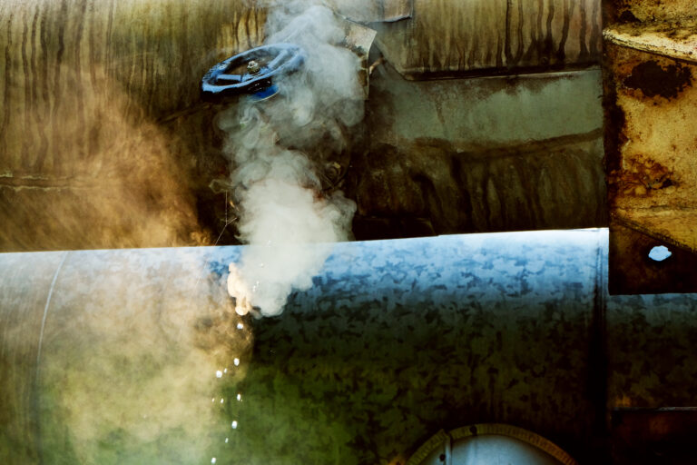
How to Prevent Catastrophic Steam Piping Accidents

How to Prevent Catastrophic Steam Piping Accidents

Table of Contents

Are you concerned about the silent dangers lurking within your industrial steam piping systems? Have you ever felt uncertain about implementing robust safety measures that protect your facility and personnel?

A single failure can lead to devastating consequences: explosions, severe burns, structural damage, prolonged downtime, and even fatalities. Relying on outdated practices or incomplete knowledge is a risk no one in charge of plant safety can afford.

But what if you could systematically address these vulnerabilities? What if you had a clear roadmap to build a safety program that significantly reducing the likelihood of catastrophic accidents?

By the end of this guide, you’ll confidently know how to identify, mitigate, and manage the risks associated with industrial steam piping. This will empower you to implement adequate preventative measures and enhance plant safety. 

Guide to Preventing Steam Piping Accidents

Implementing a comprehensive safety program for your industrial steam piping system is a multifaceted process that requires diligent planning, execution, and continuous vigilance. Follow these steps to build a robust defense against potential failures.

Steam leaking from a corroded industrial pipe, indicating a dangerous failure point in the piping system.

Conduct a Comprehensive Steam Piping Risk Assessment

Preventing catastrophic steam pipe failures begins with understanding exactly where your vulnerabilities lie. A detailed risk assessment is the foundation of any effective safety program.

What to do:

  • Identify potential hazards throughout the steam system lifecycle—from design and installation through operation and maintenance. Consider factors like material degradation (corrosion, fatigue), operational stresses (pressure, temperature cycles, vibration), external factors (support issues, insulation damage), and human error.
  • Analyze each hazard’s potential consequences, including injury, property damage, environmental impact, and business interruption.
  • Evaluate the likelihood of each hazard occurring based on historical data, system condition, operational practices, and industry experience (including lessons learned from steam pipe accidents in other facilities).
  • Combine the likelihood and consequence to determine a risk level for each identified vulnerability.
  • Prioritize risks based on severity to focus mitigation efforts where they are most needed. This is a crucial part of conducting a steam piping risk assessment effectively.

Why it matters:

A thorough risk assessment clearly shows your system’s hazards and potential impact. It moves you beyond generic safety concepts to address the actual risks present in your facility. This prioritization ensures resources are allocated efficiently to tackle the most significant threats, making your efforts to prevent steam pipe failure targeted and effective.

Ensure Proper System Design and Material Selection

The inherent safety of a steam piping system is primarily determined during its initial design and material selection. Flaws here can create latent hazards that are difficult to mitigate later.

What to do:

  • Verify that the system design follows relevant industry codes and standards (like ASME B31.1 for Power Piping or B31.3 for Process Piping) and all applicable safety regulations. This includes proper pipe sizing, routing, support structures, and thermal expansion compensation.
  • Select piping materials appropriate for the specific operating conditions (pressure, temperature, fluid properties, corrosive potential) and expected lifespan. Consider factors like susceptibility to corrosion (including galvanic corrosion if dissimilar metals are used), erosion, fatigue, and brittleness.
  • Ensure adequate provision for safety relief valves (SRVs) or pressure safety valves (PSVs) is included in the design to protect against overpressure events, which can be a primary cause of industrial steam pipe accidents.
  • Design the system with accessibility for future inspection, maintenance, and repairs.

Why it matters:

A correctly designed system using appropriate materials provides the fundamental integrity to contain high-pressure, high-temperature steam safely. Poor design or material choices can lead to premature failure, stress points, and an inability to handle operational stresses, significantly increasing the risk of leaks, ruptures, or explosions. Preventing steam pipe explosions starts with a design that accounts for all potential forces and degradation mechanisms.

Implement Robust Installation and Welding Procedures

Poor installation can compromise even the best design. Proper techniques, especially for welding, are paramount to ensuring the physical integrity of the piping system.

What to do:

  • Develop and strictly follow detailed installation procedures for proper alignment, support placement, and stress relief requirements.
  • Use qualified welders and welding procedures (WPS – Welding Procedure Specifications) that meet industry standards (like ASME Section IX or AWS D10.12).
  • Implement thorough quality control measures during installation, including visual inspections and non-destructive Testing (NDT) methods like radiography, ultrasonic testing, or dye penetrant testing on welds, especially at critical joints.
  • Ensure proper handling and storage of piping components and materials before installation to prevent damage or contamination. Avoiding certain types of contamination is crucial; while some blogs focus on high-purity systems, contamination in steam lines can also lead to corrosion and blockages, affecting safety.

Why it matters:

Incorrect installation can introduce unintended stresses, misalignment, or weak points into the system. Poor welding is a common cause of industrial pipe safety issues, leading to leaks or catastrophic failures at the joint. Ensuring high-quality installation is a direct measure for preventing steam pipe failure caused by construction defects. Safety procedures for steam pipe installation must be meticulously followed.

Establish a Rigorous Preventive Maintenance Program

Time and operational stresses wear down any piping system. A proactive, well-planned maintenance program must identify and address degradation before it leads to failure. Safety protocols for steam piping maintenance are not optional; they are mandatory.

What to do:

  • Develop a detailed preventative maintenance schedule based on the system’s design life, operating conditions, material types, and risk assessment findings.
  • These include regular inspections (internal and external), thickness measurements (using UT), and monitoring for signs of corrosion, erosion, fatigue cracking, and support degradation.
  • Plan for scheduled downtime to perform necessary repairs, component replacements (valves, traps, expansion joints), and cleaning to remove scale or deposits that can affect flow, cause water hammer, or accelerate corrosion.
  • Implement predictive maintenance techniques where feasible, such as acoustic monitoring for leaks or vibration analysis for support issues.
  • Maintain comprehensive records of all maintenance activities, including dates, findings, repairs, and who performed the work.

Why it matters:

Preventive maintenance allows you to catch potential issues when they are minor and manageable, before they escalate into critical problems. It extends the lifespan of your system and significantly reduces the risk of unexpected failures during operation. Neglecting maintenance is a common factor in industrial steam pipe accidents.

Develop Effective Operational Procedures and Training

Human factors play a significant role in industrial accidents. Proper operational procedures and thorough training ensure that the system is run safely and that personnel understand how to respond in various situations.

What to do:

  • Create clear, concise Standard Operating Procedures (SOPs) for all critical operations involving the steam system, including startup, shutdown, handling pressure/temperature changes, and isolating sections for maintenance.
  • Ensure operators understand the system’s design limits and the consequences of exceeding them.
  • Implement a comprehensive training program for all personnel interacting with or working near the steam piping system, covering hazards, safety procedures, lockout/tagout procedures, and emergency protocols.
  • Review and update SOPs and training programs regularly based on system changes, incident analysis (lessons learned from steam pipe accidents), and best practices.
  • Foster a strong safety culture where personnel are encouraged to report near misses, unusual observations, or potential hazards without fear of reprisal.

Why it matters:

Well-trained operators following established procedures are less likely to make mistakes that could compromise system integrity or lead to accidents. They are also better equipped to identify early warning signs of potential failure and respond correctly in an emergency, helping prevent steam pipe failure caused by operational errors.

Maintain Vigilant Inspection and Monitoring Practices

While preventative maintenance focuses on scheduled tasks, ongoing inspection and monitoring provide real-time awareness of the system’s condition and can detect unforeseen issues.

What to do:

  • Implement a regular industrial pipe safety inspection schedule beyond routine maintenance checks. This includes visual inspections of piping, supports, insulation, and connections.
  • Where appropriate, utilize advanced monitoring technologies, such as continuous online monitoring for steam trap performance, corrosion rates, vibration, or thermal imaging to detect hot spots or insulation damage.
  • Establish procedures for responding to alarms or unusual readings from monitoring systems.
  • Conduct internal inspections during planned outages, using visual inspection with borescopes or specialized NDT techniques to assess internal condition, especially in areas prone to corrosion or erosion.

Why it matters:

Vigilant inspection and monitoring can detect early signs of degradation or operational issues that might be missed by scheduled maintenance alone. This allows for timely intervention, preventing minor problems from escalating into significant safety hazards and preventing steam pipe accidents before they happen. Industrial pipe safety inspection is a continuous process, not a one-time event.

Establish Emergency Response and Accident Investigation Protocols

Despite all preventative efforts, accidents can still happen. Clear emergency response and investigation procedures are crucial to minimize harm and learn from incidents.

What to do:

  • Develop comprehensive emergency response plans for steam system failures (e.g., leaks, ruptures, and fires involving steam). These plans should include clear evacuation procedures, isolation protocols, and communication plans with internal teams and external emergency services.
  • Train all personnel on their roles and responsibilities during an emergency.
  • Conduct regular emergency drills to test the plan’s effectiveness and personnel readiness.
  • Establish a formal accident investigation process to determine the cause of any incident or near-miss involving the steam system.
  • Use the investigation findings (drawing lessons learned from steam pipe accidents, internal and external case studies) to update procedures, maintenance plans, and training programs to prevent recurrence

Why it matters:

A well-drilled emergency response can save lives and minimize damage if an incident occurs. A thorough investigation ensures that you learn from failures, addressing the underlying issues rather than just the symptoms, which is vital for continuous improvement in preventing steam pipe accidents.

Conclusion

Navigating the complexities of industrial steam piping safety might seem daunting, but following a structured approach can significantly reduce risks and prevent devastating accidents. Preventing steam pipe failure is not just about pipes but systems, procedures, and people.

Begin your initial assessment today and secure your facility’s future. Implementing these safety protocols for steam piping maintenance and operation is an investment that pays dividends in safety, reliability, and peace of mind. You’ve got this, and your facility’s safety depends on it.

Need expert assistance in conducting your risk assessment or developing a comprehensive safety program? Contact us now!

Know about us more 

  1. The Ultimate Guide to High-Pressure Piping: What Every Plant Manager Needs to Know
    This blog provides a comprehensive overview of high-pressure piping systems, offering essential context for understanding steam piping safety and accident prevention.
  2. Key Benefits of Professional Piping Inspection Services
    This blog highlights the importance of regular inspections, a critical strategy for preventing catastrophic steam piping accidents discussed in the blog.
  3. American Society of Mechanical Engineers (ASME) – B31.1 Power Piping
    ASME’s B31.1 standard provides authoritative guidelines for steam piping design and safety, essential for preventing accidents in high-pressure systems.
  4. U.S. Chemical Safety Board (CSB) – Steam Piping Safety Recommendations
    The CSB offers recommendations based on investigations of steam piping incidents, providing valuable insights for accident prevention.

Related Blog

Comprehensive Maintenance Checklist for Industrial Piping Systems
This blog provides a detailed checklist for maintaining piping systems, complementing the focus on preventive measures to avoid steam piping accidents.


Concerned About Steam Piping Safety?

Our experts help you prevent catastrophic steam failures with audits, maintenance plans, and safety upgrades.

The Ultimate Guide to High-Pressure Piping: What Every Plant Manager Needs to Know

The Ultimate Guide to High-Pressure Piping: What Every Plant Manager Needs to Know

Table of Contents

High-pressure piping systems are the lifelines of countless industrial facilities, silently and powerfully transporting critical fluids and gases under immense pressure. But with great power comes great responsibility – and significant risk. Plant managers face the daily challenge of ensuring these systems operate safely, efficiently, and in compliance with stringent regulations. 

One leak, one failure, can lead to catastrophic consequences: environmental disasters, worker injuries, costly downtime, and reputational damage. This isn’t a task to be taken lightly.

This ultimate guide is designed to equip plant managers with the knowledge and tools they need to master the complexities of high-pressure piping. We’ll move beyond the basics and dive deep into the nuances of design, materials, installation, maintenance, safety, and troubleshooting.

What is High-Pressure Piping?

High-pressure piping refers to piping systems that transport fluids or gases at pressures significantly higher than those found in typical low-pressure applications. There’s no universal pressure threshold that definitively labels a system “high-pressure,” but it generally implies pressures exceeding 150 psi (10 bar) and can extend into thousands of psi in specialized applications. 

Key Definitions and Terminology

  • Pressure Rating: The ability of a component or system to safely withstand maximum pressure under specified conditions is a critical parameter dictating material selection and design.
  • Nominal Pipe Size (NPS): A dimensionless number designating pipe size. It’s related to, but not always identical to, the inside or outside diameter of the pipe.
  • Schedule: A system used to indicate the wall thickness of steel pipe. Higher schedules denote thicker walls and greater pressure-handling capabilities.
  • Material Grade: Specifies the mechanical and chemical properties of the piping material, ensuring it meets the requirements for strength, corrosion resistance, and temperature tolerance.
  • Hydrostatic Testing: A non-destructive testing method used to verify the integrity of a piping system by pressurizing it with water and checking for leaks or structural weaknesses.
  • Non-Destructive Testing (NDT): A range of inspection techniques (e.g., radiography, ultrasonic testing) used to assess the condition of piping without causing damage.
  • Stress Analysis: Engineering calculations determine the stresses and strains within a piping system under various operating conditions, ensuring it can withstand the imposed loads.
High-pressure industrial piping system at an outdoor facility

Understanding Pressure and Stress

Pressure is the force exerted per unit area by a fluid or gas. In high-pressure piping, this force acts on the internal walls of the pipe, creating stress within the material. Stress is the internal resistance of the material to the applied force. When the stress exceeds the material’s yield strength, permanent deformation occurs. If the stress exceeds the ultimate tensile strength, the pipe will rupture.

The relationship between pressure, pipe diameter, and wall thickness is fundamental. As pressure increases, either the pipe diameter must decrease, or the wall thickness must increase to maintain a safe stress level. This relationship is governed by various design codes and standards (discussed later).

Relevant Codes and Standards

Adherence to recognized codes and standards is paramount in high-pressure piping. These documents provide detailed design, materials, fabrication, inspection, and testing requirements. Key organizations and their relevant standards include:

  • ASME (American Society of Mechanical Engineers): ASME B31.1 (Power Piping), ASME B31.3 (Process Piping), ASME Boiler and Pressure Vessel Code (BPVC). These standards are widely used across various industries.
  • ANSI (American National Standards Institute): ANSI standards often cross-reference ASME standards and address specific aspects of piping components.
  • API (American Petroleum Institute): API standards are prevalent in the oil and gas and cover pipeline design, construction, and operation topics.
  • ISO (International Organization for Standardization): ISO standards provide a global framework for piping system requirements.
  • Local Regulations: Plant managers must also know and comply with local, state, and national regulations governing high-pressure piping within their jurisdiction.

Key Components of High-Pressure Piping Systems

A high-pressure piping system is more than just pipes. It’s a complex assembly of interconnected components, each vital in ensuring safe and efficient operation. Understanding these components and their functions is essential for effective management.

Pipes

The primary conduit for transporting fluids or gases. Pipe material selection is critical and depends on the fluid, pressure, temperature, and corrosion potential. Common materials include:

  • Carbon Steel: Economical and widely used for many applications, but susceptible to corrosion.
  • Alloy Steel: Offers improved strength, corrosion resistance, and high-temperature performance compared to carbon steel.
  • Stainless Steel: Provides excellent corrosion resistance, making it suitable for demanding applications.
  • Special Alloys: These are used in extreme conditions where other materials are inadequate (e.g., titanium, nickel alloys).
Stainless steel piping system inside an industrial facility

Fittings

Used to connect pipe sections, change direction, and branch off the main line. Common types include:

  • Elbows: Change the flow direction (45°, 90°, 180°).
  • Tees: Branch off the main line at a 90° angle.
  • Reducers: Change the pipe diameter (concentric or eccentric).
  • Couplings: Connect two pipes of the same diameter.
3D rendered stainless steel pipe fittings and valves with red handles

Valves

Control the flow of fluids or gases within the system. Different valve types are suited for various applications:

  • Gate Valves: Used for on/off control, providing minimal flow restriction when fully open.
  • Globe Valves: Used for throttling flow, providing more precise control.
  • Ball Valves: Provide quick on/off control with minimal pressure drop.
  • Check Valves: Prevent backflow in the system.
  • Pressure Relief Valves (PRVs): Protect the system from overpressure by automatically releasing excess pressure.
Industrial control valves with blue wheels connected to yellow steel pipelines

Flanges

Connect pipe sections, valves, and other equipment. They provide a strong, leak-tight seal and allow for easy disassembly for maintenance. Flange ratings must match the system pressure. Common types include:

  • Welding Neck Flanges: Welded to the pipe, providing excellent strength and leak resistance.
  • Slip-On Flanges: Slide over the pipe and are welded in place.
  • Threaded Flanges: Screw onto the pipe, used for lower-pressure applications.
Stacks of industrial round steel flanges and fittings at a construction site

Gaskets

Used to create a seal between flanges. Gasket material must be compatible with the fluid and temperature.

Close-up view of serrated industrial pipe gaskets stacked together

Supports and Hangers

Provide structural support for the piping system, preventing sagging, vibration, and excessive stress. Support design is critical for high-pressure systems to account for the weight of the pipe, fluid, and insulation, as well as thermal expansion and contraction.

Bundled metal pipes stored on a multi-level industrial racking system

High-Pressure Piping Design Considerations

Designing a safe and reliable high-pressure piping system requires careful consideration of various factors, from material selection to stress analysis. Errors in design can lead to catastrophic failures, emphasizing the importance of meticulous planning.

Material Selection for High-Pressure Piping

Choosing the right material is paramount. Consider these factors:

    • Pressure and Temperature: The material must withstand the maximum operating pressure and temperature.
    • Fluid Compatibility: The material must resist corrosion and degradation from the transported fluid.
    • Mechanical Properties: The material must have sufficient yield strength, tensile strength, and ductility to withstand the stresses imposed by the system.
    • Weldability: The material must be easily weldable if welding is required for fabrication.
    • Cost: Balance performance requirements with cost considerations.

Pipe Wall Thickness Calculation

The required pipe wall thickness is determined by the internal pressure, pipe diameter, material strength, and a safety factor. Design codes like ASME B31.3 provide equations for calculating the minimum required wall thickness. These calculations must account for corrosion allowance to compensate for material loss over time.

Stress Analysis of High-Pressure Piping

Stress analysis is crucial to ensure the piping system can withstand the stresses induced by pressure, temperature variations, and external loads. Common methods include:

  • Static Analysis: Determines the stresses caused by steady-state conditions (pressure, weight).
  • Thermal Analysis: Evaluates the stresses caused by thermal expansion and contraction.
  • Dynamic Analysis: Assesses the stresses caused by dynamic loads such as vibration and seismic activity.

Software tools are commonly used to perform detailed stress analysis and identify potential weak points in the design.

Support Design and Placement

Proper support design is essential to minimize stress and prevent excessive deflection. Supports must be strategically placed to distribute the load evenly and to avoid sagging. Considerations include:

  • Support Spacing: Determined by the pipe diameter, material, and fluid density.
  • Support Type: Rigid, spring, and sliding supports are used depending on the application and thermal expansion requirements.
  • Anchor Points: Fixed points that prevent movement in all directions.

Code Compliance and Documentation

All design calculations, material specifications, and drawings must comply with relevant codes and standards (e.g., ASME B31.3). Thorough documentation is essential for traceability, maintenance, and future modifications.

Best Practices for High-Pressure Piping Installation

Even the best-designed system can fail if installed improperly. Adhering to best practices during installation is critical for ensuring long-term reliability and safety.

Qualified Personnel and Training

Installation should be performed by qualified, experienced personnel thoroughly trained in high-pressure piping techniques, including welders certified to the appropriate standards.

Welding Procedures and Qualifications

Welding is a critical aspect of high-pressure piping installation. Welding procedures must be qualified according to ASME Section IX or other relevant standards, and welders must be certified to perform the specific welding procedures used.

Material Handling and Storage

Piping materials must be handled and stored carefully to prevent damage and contamination. Protect pipes from moisture, corrosion, and physical damage.

Pipe Cutting and Preparation

Pipes must be cut accurately and appropriately prepared for welding or joining. Ensure the pipe ends are clean, square, and free of burrs.

Alignment and Fit-Up

Proper alignment and fit-up are essential for achieving sound welds and minimizing stress. Before welding, use clamps and other tools to ensure correct alignment.

Inspection and Testing During Installation

During installation, regular inspections should be performed to verify compliance with design requirements and welding procedures. Non-destructive testing (NDT) methods such as radiography and ultrasonic testing should be used to inspect welds for defects.

Pressure Testing After Installation

After installation, the piping system must be pressure tested to verify its integrity. Hydrostatic testing is the most common method, involving pressurizing the system with water and checking for leaks. Pneumatic testing (air or gas) can also be used, but it carries a higher risk and requires additional safety precautions.

High-Pressure Piping Maintenance: Ensuring Reliability

Regular maintenance is crucial for preserving the integrity and reliability of high-pressure piping systems. A proactive maintenance program can prevent failures, extend the system’s lifespan, and ensure safe operation.

Importance of Regular Inspections

Regular inspections are the cornerstone of a successful maintenance program. Qualified personnel should perform inspections and cover all critical components of the system.

Visual Inspection Techniques

Visual inspection can identify many potential problems, such as:

  • Corrosion: Look for signs of rust, pitting, and other forms of corrosion.
  • Leaks: Check for drips, stains, or other evidence of leaks.
  • Damage: Inspect for dents, cracks, and other physical damage.
  • Support Issues: Verify that supports are in good condition and properly aligned.

Non-Destructive Testing (NDT) Methods for High-Pressure Piping

NDT methods are used to assess the condition of piping without causing damage. Common techniques include:

    • Radiography (RT): Uses X-rays or gamma rays to detect internal defects in welds and pipe walls.
    • Ultrasonic Testing (UT): Uses sound waves to detect internal defects and measure wall thickness.
    • Magnetic Particle Testing (MT): Detects surface cracks in ferromagnetic materials.
    • Liquid Penetrant Testing (PT): Detects surface cracks in non-ferromagnetic materials.
    • Infrared Thermography: Detects temperature variations that may indicate leaks or insulation problems.

Leak Detection Methods for High-Pressure Piping

Early leak detection is crucial for preventing major failures. Common methods include:

    • Pressure Monitoring: Continuously monitoring the system pressure can detect gradual leaks.
    • Acoustic Monitoring: Listening for the sound of escaping fluids or gases.
    • Tracer Gas Detection: Introducing a tracer gas into the system and using a sensor to detect leaks.

Corrosion Prevention and Control

Corrosion is a significant threat to high-pressure piping. Effective corrosion prevention strategies include:

    • Material Selection: Choosing corrosion-resistant materials.
    • Protective Coatings: Applying coatings to protect the pipe surface.
    • Cathodic Protection: Using electrical currents to prevent corrosion.
    • Chemical Treatment: Adding chemicals to the fluid to inhibit corrosion.

Repair and Replacement Procedures

When damage or deterioration is detected, timely repairs or replacements are essential. Repairs must be performed according to qualified procedures and standards, and replacement components must meet the original design specifications.

High-Pressure Piping Safety: Mitigating Risks

Safety is paramount in high-pressure piping operations. Comprehensive safety protocols are essential for protecting personnel, equipment, and the environment.

Hazard Identification and Risk Assessment

A thorough hazard identification and risk assessment should be conducted to identify potential safety hazards associated with the high-pressure piping system. This includes:

    • Pressure Hazards: Ruptures, leaks, and explosions.
    • Fluid Hazards: Exposure to toxic or flammable fluids.
    • Mechanical Hazards: Moving parts, falling objects.
    • Environmental Hazards: Spills and releases.

Personal Protective Equipment (PPE)

Appropriate PPE must be worn by all personnel working on or near high-pressure piping systems. This may include:

    • Safety Glasses or Face Shields: To protect against flying debris and fluid splashes.
    • Gloves: To protect against chemical exposure and burns.
    • Hearing Protection: To protect against noise from leaks or equipment.
    • Protective Clothing: To protect against chemical exposure and physical hazards.

Lockout/Tagout Procedures

Lockout/tagout (LOTO) procedures must be implemented to prevent equipment’s accidental start-up during maintenance or repair activities.

Emergency Shutdown Procedures

Emergency shutdown procedures must be in place to quickly isolate and depressurize the system in case of a leak or other emergency.

Training and Awareness

All personnel working on or near high-pressure piping systems must be thoroughly trained in safety procedures and hazard awareness. Regular refresher training should be provided.

Regulatory Compliance

Plant managers must ensure compliance with all applicable safety regulations and standards.

Conclusion

Mastering high-pressure piping systems is a demanding but essential undertaking for plant managers. By understanding the foundational concepts, key components, design considerations, installation best practices, maintenance strategies, safety protocols, and troubleshooting techniques outlined in this ultimate guide, you are well-equipped to manage your systems effectively. This knowledge empowers you to minimize risks, optimize performance, and ensure the long-term reliability of your high-pressure piping infrastructure.

Remember that staying informed about future trends and innovations and partnering with experts are critical for continued success.

Explore SRJ Piping India‘s comprehensive range of solutions for high-pressure piping and contact our experts for a consultation to optimize your system and ensure safe, reliable operations. For more detailed information, contact us now

High-pressure piping systems are silent profit killers—every 1% efficiency drop in your 350-bar network leaks ₹2.8Cr annually in lost steam and unscheduled downtime. The ASME B31.3-2024 Code now mandates digital twin monitoring for all Class 1 systems, while OISD-STD-141 requires ultrasonic thickness testing at 500-hour intervals—standards we enforce through our AI-Driven Pipe Integrity Platform. When a Tamil Nadu fertilizer plant’s 20-year-old carbon steel line ruptured at 289 bar (₹176Cr loss, per PNG Study), it validated our 5-Stage High-Pressure Protocol:

  1. Smart Material Selection (ASTM A106 Grade C vs. SCH 160 wall thickness)

  2. Finite Element Analysis (CAESAR II stress simulations)

  3. Robotic Weld Inspection (Phased Array UT + AI defect detection)

  4. Live Pressure Analytics (IoT-enabled vibration monitoring)

  5. Predictive Replacement (Machine learning corrosion modeling)

Your piping isn’t just moving fluid—it’s transporting risk or reward.

Managing High-Pressure Piping Systems?

Get expert help from SRJ Piping India to assess system risks, ensure safety, and keep your high-pressure network running smoothly.

Carbon Steel vs. Stainless Steel Piping: The Ultimate Guide for Industrial Facilities

Carbon Steel vs. Stainless Steel Piping: The Ultimate Guide for Industrial Facilities

Table of Contents

Choosing the right piping material for your industrial facility is a critical decision with long-lasting consequences. From the initial investment to long-term maintenance and operational efficiency, the pipe material dictates the performance and safety of your entire system. While numerous options exist, carbon steel and stainless steel are the most prevalent choices, each offering unique advantages and disadvantages. 

This comprehensive guide is the definitive resource for navigating the complexities of carbon steel and stainless steel piping. Whether you’re a seasoned engineer or new to the field, this guide will equip you with the knowledge to select the optimal piping material for your industrial application.

What is Carbon Steel?

Carbon steel is an alloy of iron and carbon, with carbon being the primary alloying element. The percentage of carbon significantly influences the steel’s properties, such as hardness and strength. Generally, carbon steel is categorized into four classes based on carbon content:

  • Low-carbon steel (Mild Steel) contains up to 0.3% carbon. It is easily weldable, machinable, and relatively inexpensive, making it a common choice for various structural applications.
  • Medium Carbon Steel contains 0.3% to 0.6% carbon. It balances strength and ductility and is often used for machine parts and automotive components.
  • High-carbon steel contains 0.6% to 1.0% carbon. It is tough, wear-resistant, and suitable for tools, dies, and springs.
  • Very High-Carbon Steel contains 1.0% to 2.0% carbon. It is used for specialized applications requiring extreme hardness and wear resistance, such as cutting tools and high-strength wires.
Stacked rectangular and square steel pipes organized in an industrial warehouse

Key Characteristics of Carbon Steel

  • High Strength and Hardness: Carbon steel offers excellent mechanical properties, particularly in higher carbon grades.
  • Cost-Effectiveness: Generally less expensive than stainless steel, making it an attractive option for budget-conscious projects.
  • Good Machinability and Weldability: Low carbon grades allow for easy fabrication and installation.
  • Susceptibility to Corrosion: Carbon steel is prone to rust and corrosion in the presence of moisture and certain chemicals, limiting its use in corrosive environments.

What is Stainless Steel?

Stainless steel is a steel alloy containing a minimum of 10.5% chromium. The chromium forms a passive layer of chromium oxide on the surface, which protects the steel from corrosion. Other alloying elements, such as nickel, molybdenum, and titanium, are often added to enhance strength, weldability, and resistance to specific corrosive agents.

Stainless steel is categorized into several types, each with a unique combination of properties and applications:

  • Austenitic Stainless Steel: The most common type, containing chromium and nickel. Known for excellent corrosion resistance, high ductility, and weldability. Examples include 304 and 316 stainless steel.
  • Ferritic Stainless Steel: Contains chromium but little or no nickel. It is magnetic, less expensive than austenitic grades, and offers good corrosion resistance.
  • Martensitic Stainless Steel: Contains chromium and can be hardened by heat treatment. It is magnetic and offers moderate corrosion resistance.
  • Duplex Stainless Steel: A combination of austenitic and ferritic structures, offering high strength and excellent corrosion resistance, particularly in chloride environments.
Complex stainless steel piping network inside a modern industrial processing facility

Key Characteristics of Stainless Steel

  • Exceptional Corrosion Resistance: The high chromium content protects against rust and corrosion.
  • High Strength and Ductility: Stainless steel offers a good balance of strength and formability.
  • Hygienic Properties: Its smooth, non-porous surface makes it easy to clean and sanitize, ideal for food processing and pharmaceutical applications.
  • Aesthetic Appeal: Stainless steel’s bright, clean appearance makes it a popular choice for architectural and decorative applications.
  • Higher Cost: Generally more expensive than carbon steel due to the addition of chromium and other alloying elements.

Difference Between Carbon Steel and Stainless Steel Piping

Understanding the differences between carbon steel and stainless steel is essential for selecting the appropriate material for your industrial piping system.

Composition

Carbon Steel: Primarily iron and carbon, with trace amounts of other elements. The carbon content dictates the steel’s hardness and strength.

Stainless Steel: Contains a minimum of 10.5% chromium, which forms a passive layer for corrosion resistance. It may also include nickel, molybdenum, and other elements for enhanced properties.

Corrosion Resistance

Carbon Steel: Susceptible to rust and corrosion, especially in humid or chemically aggressive environments. Requires protective coatings or treatments.

Stainless Steel: Highly corrosion-resistant due to the chromium oxide layer, making it suitable for corrosive and hygienic applications.

Strength and Hardness

Carbon Steel: Offers high strength and hardness, particularly in higher carbon grades.

Stainless Steel: Provides a good balance of strength and ductility, with specific grades offering exceptional strength (e.g., duplex stainless steel).

Weldability

Carbon Steel: Generally easy to weld, especially low carbon grades.

Stainless Steel: Requires specialized welding techniques to maintain corrosion resistance and prevent sensitization.

Cost

Carbon Steel: Typically less expensive than stainless steel.

Stainless Steel: More expensive due to the addition of chromium and other alloying elements.

Applications

Carbon Steel: Used in applications where corrosion is not a primary concern, such as structural supports, pipelines for non-corrosive fluids, and general construction.

Stainless Steel: Ideal for corrosive environments, high-temperature applications, hygienic processes, and architectural applications where aesthetics are essential.

Maintenance

Carbon Steel: Requires regular inspection and maintenance to prevent corrosion, including painting, coating, or cathodic protection.

Stainless Steel: Requires less maintenance due to its inherent corrosion resistance.

Lifespan

Carbon Steel: Shorter lifespan in corrosive environments unless properly protected.

 Stainless Steel: Longer lifespan due to its corrosion resistance.

Applications: Where Carbon Steel and Stainless Steel Shine

The choice between carbon steel and stainless steel hinges significantly on the specific application and the environment in which the piping system will operate. Let’s explore some typical industrial applications for each material.

Carbon Steel Applications

  • Water Pipelines: For transporting potable water and wastewater in non-corrosive environments.
  • Natural Gas Pipelines: For transporting natural gas over long distances.
  • Structural Applications: Used extensively in construction, bridges, and other structural supports.
  • Oil and Gas Industry: For transporting crude oil and natural gas in less corrosive environments. Requires corrosion inhibitors and regular inspection.
  • HVAC Systems: For chilled water and heating water distribution in closed-loop systems where corrosion is minimized.
  • Fire Protection Systems: Widely used in fire sprinkler systems due to their strength and cost-effectiveness, but require corrosion-resistant coatings.

Stainless Steel Applications

  • Chemical Processing: For handling corrosive chemicals, acids, and alkalis. Different grades of stainless steel are selected based on the specific chemical compatibility.
  • Food and Beverage Industry: For processing and transporting food products, beverages, and dairy products, due to its hygienic properties and corrosion resistance.
  • Pharmaceutical Industry: Manufacturing and transporting pharmaceuticals require high purity and corrosion resistance to prevent contamination.
  • Marine Environments: Due to its resistance to saltwater corrosion, it is used for shipbuilding, offshore platforms, and seawater piping systems.
  • Wastewater Treatment: For handling corrosive wastewater and sewage.
  • High-Temperature Applications: High temperatures and corrosive environments are present in power plants, refineries, and other industries.
  • Medical Implants and Instruments: Due to their biocompatibility and corrosion resistance.

Cost Analysis: Carbon Steel vs. Stainless Steel Pipe

While initial cost is a significant factor, a comprehensive cost analysis must consider the entire lifecycle of the piping system. This includes material, installation, maintenance, and potential costs associated with downtime due to corrosion or failure.

Initial Material Cost

Carbon Steel: Generally less expensive than stainless steel, offering a lower upfront investment.

Stainless Steel: More expensive due to the higher cost of chromium and other alloying elements.

Installation Costs

Carbon Steel: Easier to weld and fabricate, potentially leading to lower installation costs.

Stainless Steel: Requires specialized welding techniques, which may increase labor costs.

Maintenance Costs

Carbon Steel: Higher maintenance costs due to the need for regular inspection, painting, coating, or cathodic protection to prevent corrosion.

Stainless Steel: Lower maintenance costs due to its inherent corrosion resistance.

Lifecycle Costs

Carbon Steel: Lower initial cost but potentially higher lifecycle costs due to maintenance and potential replacement due to corrosion.

Stainless Steel: Higher initial cost but potentially lower lifecycle costs due to reduced maintenance and longer lifespan.

Cost-Benefit Analysis

A thorough cost-benefit analysis should consider the following factors:

  • Operating Environment: The level of corrosivity in the environment.
  • Fluid Properties: The chemical properties of the fluid being transported.
  • Operating Temperature: The temperature range of the fluid and the environment.
  • System Lifespan: The expected lifespan of the piping system.
  • Downtime Costs: The potential costs associated with downtime due to corrosion or failure.
  • Safety Requirements: The safety implications of a piping system failure.

Advanced Strategies & Best Practices

Beyond the basic material selection, several advanced strategies and best practices can optimize the performance and lifespan of your industrial piping system.

Specialized Coatings for Carbon Steel

  • Epoxy Coatings: Provide excellent corrosion and chemical resistance for carbon steel pipes.
  • Polyurethane Coatings: Offer high abrasion resistance and UV protection for outdoor applications.
  • Galvanizing: A zinc coating that provides sacrificial protection against corrosion.
Worker spray-painting a steel frame with protective coating using an industrial spray gun

Surface Treatments for Stainless Steel

  • Passivation: A chemical treatment that enhances the chromium oxide layer on stainless steel, improving corrosion resistance.
  • Electropolishing: A process that removes surface imperfections, creating a smooth, hygienic surface ideal for food processing and pharmaceutical applications.
Worker manually painting a steel structure with corrosion-resistant coating using a brush

Welding Techniques for Stainless Steel

  • Gas Tungsten Arc Welding (GTAW/TIG): Provides precise control and high-quality welds, minimizing the risk of sensitization and corrosion.
  • Gas Metal Arc Welding (GMAW/MIG): A faster welding process for thicker stainless steel pipes.
  • Proper Shielding Gas: The correct shielding gas (e.g., argon, helium) is crucial to prevent oxidation and contamination during welding.
Technician performing TIG welding on stainless steel pipe using argon gas in a workshop

Non-Destructive Testing (NDT)

  • Radiographic Testing (RT): Uses X-rays or gamma rays to detect internal flaws in welds and pipes.
  • Ultrasonic Testing (UT): Uses sound waves to detect surface and subsurface defects.
  • Liquid Penetrant Testing (PT): Detects surface cracks and discontinuities.
  • Magnetic Particle Testing (MT): Detects surface and subsurface flaws in ferromagnetic materials (e.g., carbon steel, martensitic stainless steel).
Engineer in red safety gear inspecting industrial piping system using a digital tablet

Cathodic Protection for Buried Pipelines

  • Sacrificial Anodes: Using more reactive metals (e.g., zinc, magnesium) to protect carbon steel pipelines from corrosion.
  • Impressed Current Cathodic Protection (ICCP): Using an external power source to provide cathodic protection.
Close-up of metallic float valves regulating water levels in a plumbing system

Future Trends & Innovations in Piping Materials

The industrial piping industry constantly evolves, with new materials, technologies, and regulations shaping the future.

Advanced Stainless Steel Alloys

  • High-Strength Stainless Steels: Offering increased strength and reduced weight for demanding applications.
  • Nitrogen-Enhanced Stainless Steels: Providing improved corrosion resistance and strength.

Composite Materials

  • Fiber-Reinforced Polymer (FRP) Pipes: Lightweight, corrosion-resistant alternatives to steel pipes.
  • Thermoplastic Pipes: Offering excellent chemical resistance and flexibility.

Additive Manufacturing (3D Printing)

  • Custom Piping Components: 3D printing allows for creating complex and customized piping components on demand.
  • On-Site Manufacturing: Reduces lead times and transportation costs.

Smart Piping Systems

  • Sensors and Monitoring Systems: Real-time monitoring of pressure, temperature, flow rate, and corrosion.
  • Predictive Maintenance: Using data analytics to proactively predict potential failures and schedule maintenance.

Sustainable Materials

  • Recycled Steel: Using recycled steel to reduce the environmental footprint of piping systems.
  • Bio-Based Polymers: Developing sustainable alternatives to traditional plastic pipes.

Impact of Environmental Regulations

  • Stricter Emission Standards: Requiring more corrosion-resistant materials to prevent leaks and spills.
  • Water Conservation: Promoting the use of closed-loop systems and water-efficient piping solutions.

Choosing the Right Piping Material for Your Facility

Selecting the optimal piping material requires a systematic approach, considering various factors and prioritizing your needs.

  • Define the Application: Identify the piping system’s intended use, including the type of fluid transported, the operating temperature, and the pressure requirements.
  • Assess the Environment: Evaluate the environment’s corrosivity, including humidity, chemical exposure, and potential for erosion.
  • Consider Regulatory Requirements: Ensure compliance with all applicable industry standards and regulations.
  • Evaluate Material Properties: Compare the properties of carbon steel and stainless steel, including corrosion resistance, strength, weldability, and cost.
  • Perform a Cost-Benefit Analysis: Evaluate each material’s total lifecycle costs, considering initial investment, maintenance, and potential downtime.
  • Consult with Experts: Seek advice from experienced engineers and piping specialists to ensure the optimal material selection.

Key Considerations

  • Corrosion Resistance: Prioritize stainless steel in corrosive environments.
  • Cost: Consider carbon steel for less demanding applications.
  • Hygienic Requirements: Choose stainless steel for food processing and pharmaceutical applications.
  • Temperature: Select materials that can withstand the operating temperature range.
  • Pressure: Ensure the material can handle the system’s pressure requirements.
  • Maintenance: Consider the long-term maintenance costs associated with each material.
  • Lifespan: Factor in the expected lifespan of the piping system.
  • Sustainability: Consider the environmental impact of each material.

Conclusion

Selecting the right piping material is a critical decision that impacts your industrial facility’s safety, efficiency, and longevity. This ultimate guide has provided a comprehensive overview of carbon steel and stainless steel piping, exploring their properties, applications, cost considerations, and future trends.

By understanding the nuanced differences between these materials and employing a systematic approach to material selection, you can ensure your piping system’s optimal performance and reliability.

Explore SRJ Piping India‘s comprehensive range of solutions to find the perfect fit for your industrial needs. Contact our experts for a consultation to receive personalized guidance and support.

The Carbon Steel vs. Stainless Steel debate isn’t about material—it’s about operational survival. While ASTM A106 Carbon Steel saves 40% upfront costs, ASTM A312 Stainless delivers 8-12x lifespan in corrosive environments—a tradeoff we optimize through our Material Selection AI Platform. When a Visakhapatnam refinery’s carbon steel pipeline failed after 18 months (₹92Cr loss, per PNGRB Incident Report), it validated our 3D Corrosion Mapping System that predicts failure points with 94% accuracy. Your ideal choice hinges on five hidden factors most vendors ignore:

  1. Chloride Stress Corrosion Cracking Risk (SS316L vs. CS + FBE coating)

  2. Cyclic Fatigue Requirements (ASTM A790 duplex alternatives)

  3. Bacterial Corrosion Potential (MIC resistance testing)

  4. Total Cost of Ownership (Our TCO Calculator)

  5. Regulatory Triggers (OISD-118 vs. API 570 inspection intervals)

This isn’t metallurgy—it’s financial risk management with a 20-year horizon.

Need Help Choosing the Right Piping Material?

Our piping experts will guide you through selecting the best material—carbon steel or stainless steel—for your facility’s performance, environment, and budget.

Preventing HVAC Piping Disasters: Your Comprehensive How-To Guide

Preventing HVAC Piping Disasters: Your Comprehensive How-To Guide

Table of Contents

HVAC piping is critical for climate control, but common failures—like leaks, bursts, clogs, and corrosion—can lead to costly damage and system breakdowns. Often, these issues arise from poor installation or neglected maintenance. 

This guide provides homeowners, building managers, and installers with a comprehensive, step-by-step approach to preventing such disasters. It covers material selection, installation techniques, inspection, and maintenance to ensure efficient, safe, and leak-free HVAC operation.

Let’s dive in and equip you with the knowledge to avert potential HVAC piping disasters.

Understanding the Foundations: HVAC Piping Systems

Before we delve into preventing failures, it’s essential to understand the different types of piping within an HVAC system and their specific roles. Most HVAC systems utilize one or more of the following piping networks:

Refrigerant Lines

These are the most critical pipes in many HVAC systems (like central air conditioners and heat pumps). They form a closed loop carrying refrigerant between the indoor coil (evaporator) and the outdoor unit (condenser). This refrigerant undergoes phase changes (from liquid to gas and back) to absorb and release heat, effectively cooling or heating your space. 

"HVAC technicians inspecting and servicing gas water heaters and piping systems indoors"

Condensate Drains

As the evaporator coil cools the air, moisture is removed through condensation. This water collects in a drain pan beneath the coil and needs to be safely channeled away. Condensate drain lines typically use gravity to move the water to a drain, sump pump, or outdoors. These lines are often made of PVC or CPVC and are susceptible to algae, mold, dirt, and debris clogs.

"Damaged pipeline with visible hole and water leakage on white background"

Hydronic Piping

Common in boilers, chillers, and radiant heating/cooling systems, hydronic piping circulates heated or chilled water (or a water/glycol mixture) throughout a building to provide comfort. Depending on temperature, pressure, and application, these systems can involve various materials, including copper, steel, PEX, and even specialized plastics. 

"Complex water piping network showing multiple flow control valves and junctions"

Ventilation Ducting

While not strictly “piping” traditionally, ductwork is crucial for delivering conditioned air. Problems like leaks, poor sealing, or improper duct sizing can significantly impact system performance and energy efficiency, sometimes leading to issues that might be initially mistaken for other HVAC system piping problems.

"Illustration of a modern HVAC duct connected to ceiling air vents in a commercial building"

HVAC Piping Failures and Their Real-World Impact

Understanding what can go wrong is the first step in preventing it. Based on industry experience and common HVAC pipe installation issues, here are the most frequent types of piping failures:

Refrigerant Leaks

This is one of the most common and damaging failures. Refrigerant is essential for the system’s operation, and leaks lead to:

  • Reduced cooling/heating capacity
  • Increased energy bills (system works harder)
  • Potential compressor damage (as it operates without enough refrigerant)
  • Environmental harm (depending on the refrigerant type)

Causes often include:

  • Improperly made flared or soldered joints during installation
  • Vibration causing wear or loosening connections
  • Corrosion (especially formic acid corrosion on copper)
  • Mechanical damage (e.g., someone accidentally hitting the line)
  • Material defects

Condensate Drain Clogs and Backups

Algae, mold, sludge, and debris can easily build up in a condensate drain line’s warm, wet environment. A clog leads to:

  • Water is backing up into the drain pan
  • Overflowing drain pan, causing water damage to ceilings, walls, or flooring
  • System shutdown (many systems have float switches that kill power when the pan fills)
  • Mold and mildew growth (air quality issues)

Causes:

  • Lack of regular cleaning and maintenance
  • Improper slope of the drain line
  • No trap or an improperly installed trap (prevents proper drainage and allows air infiltration)
  • Debris entering the drain pan

Corrosion

Corrosion can affect metal pipes (copper, steel) in refrigerant and hydronic systems, leading to leaks and material degradation.

  • Leaks (pinholes or larger)
  • Reduced flow (internal scaling/corrosion)
  • System failure

Causes:

  • Galvanic corrosion (dissimilar metals in contact)
  • Formic acid corrosion (“ant nest” corrosion) on copper refrigerant lines (often linked to volatile organic compounds – VOCs)
  • Internal corrosion in hydronic systems (improper water treatment, dissolved oxygen)
  • External corrosion from environmental factors (salt air, pollutants)

Improper Jointing

Mistakes are a primary source of leaks and failures in soldering, brazing, solvent welding, and mechanical connections.

  • Leaks (refrigerant, water)
  • Weak points susceptible to future failure
  • Reduced system pressure/flow

Causes:

  • Poor surface preparation (not cleaning/deburring pipes)
  • Using the wrong flux or solder/brazing alloy
  • Insufficient or excessive heat
  • Inadequate application of solvent cement (PVC/CPVC)
  • Over-tightening or under-tightening mechanical fittings
  • Using incorrect fittings for the pipe material.

Mechanical Damage & Lack of Support

Pipes need proper support to prevent sagging, joint stress, and damage from vibration or external forces.

  • Leaks at stressed joints
  • Pipe rupture
  • Damage from rubbing/vibration

Causes:

  • Insufficient hangers or supports
  • Incorrect type of support
  • Pipes being stepped on or hit
  • Vibration from the unit is transferred to the unsupported pipes

Material Incompatibility or Incorrect Selection

Using the wrong pipe material for the application’s pressure, temperature, fluid type, or environmental conditions is a recipe for failure.

  • Rapid degradation of the pipe
  • Leaks or bursts
  • System contamination

Causes:

  • Using PVC (drainage) for pressurized applications
  • Using materials susceptible to the transported fluid (e.g., certain plastics with specific chemicals)
  • Using materials that cannot withstand the operating temperature or pressure
  • Placing materials in incompatible environments (e.g., non-UV-rated pipe in sunlight)

The Consequences: Why Preventing Failures Matters

Beyond the immediate inconvenience, HVAC piping system problems lead to significant adverse outcomes:

  • Financial Costs: Repairing leaks, replacing damaged components (like compressors), extensive water damage restoration (drywall, flooring, insulation, electrical), mold remediation, and increased energy bills. 
  • Reduced System Performance & Lifespan: Leaks or clogs force the system to work harder, reducing efficiency, increasing wear and tear, and shortening the HVAC unit’s overall life.
  • Health & Safety Risks: Water leaks promote mold and mildew growth, negatively impacting indoor air quality and potentially causing respiratory issues. 
  • Operational Disruptions: In commercial and industrial settings, HVAC failures can halt operations, damage sensitive equipment, and impact productivity, leading to significant financial losses beyond repair costs.

The cost of prevention is minuscule compared to recovery from a major piping disaster. Now, let’s focus on the ‘How-To’.

Preventing HVAC Piping Failures: A Step-by-Step Guide

Preventing piping failures starts long before the system is even turned on. It involves careful planning, skilled installation, proper material selection, and diligent ongoing maintenance. Follow these steps to minimize your risk:

Meticulous Planning and Design

This is where the foundation for a reliable piping system is laid. Don’t rush this phase.

  • System Sizing and Layout: Ensure the HVAC system (and thus the piping) is correctly sized for the space. An undersized or oversized system can cause operational stress that indirectly affects piping over time. 
  • Choosing the Right Material for HVAC Piping: This decision directly impacts system longevity and performance. 

Material selection depends on several factors:

  • Fluid Type: Refrigerant, water (potable, closed-loop hydronic), condensate.
  • Operating Temperature and Pressure: Different materials have different ratings. Refrigerant lines require materials rated for high pressure, and hot water hydronic systems need materials that can handle elevated temperatures.
  • Environmental Conditions: Is the pipe exposed to UV light (sunlight), corrosive chemicals (indoor or outdoor), or extreme temperature fluctuations?
  • Code Requirements: Local building codes specify approved materials and installation methods.
  • Cost: Initial material cost vs. long-term durability and installation complexity.

Let's look at common materials:

  • Copper: Excellent for refrigerant lines due to its workability and ability to withstand high pressure and temperature fluctuations. 
  • PEX (Cross-linked Polyethylene): Flexible plastic tubing, primarily used in hydronic heating/cooling and potable water systems. 
  • PVC (Polyvinyl Chloride): Rigid plastic pipe, almost exclusively used for non-pressurized condensate drains. 
  • CPVC (Chlorinated Polyvinyl Chloride): Similar to PVC but can handle higher temperatures and slightly higher pressures. 
  • Steel (Black Steel, Galvanized Steel): Used in high-pressure or large-diameter hydronic systems, especially in commercial/industrial settings.

Executing Quality Installation Practices

Even the best design can be undone by poor workmanship. Quality HVAC pipe installation is paramount.

  • Hire Qualified Professionals: For complex systems like refrigerant lines or hydronic loops, always use licensed and experienced HVAC technicians. 
  • Proper Cutting and Deburring: Pipes must be cut squarely using appropriate tools (tubing cutter for copper/PEX, saw for plastics).

Mastering Joining Techniques:

  • Soldering/Brazing (Copper): This requires skill. Surfaces must be clean. Use appropriate flux and solder/brazing alloy for the application. 
  • Solvent Welding (PVC/CPVC): Use the correct primer and solvent cement for the specific pipe material and size. 
  • Mechanical Fittings (Flared, Compression, Press-Connect, PEX Crimp/Expansion): Follow manufacturer instructions precisely. 
  • Ensuring Correct Slope (Condensate): Gravity drain lines must have a continuous downward slope from the drain pan to the discharge point. 

Material-Specific Installation Considerations

Each material has nuances that must be respected during installation.

  • Copper: Avoid using excessive flux, especially inside the pipe, as residue can contribute to formicary corrosion.
  • PEX: Do not exceed the recommended bend radius to prevent kinking. When using specific compression fittings, use stiffeners inside the pipe ends.
  • PVC/CPVC: Ensure the pipe ends are clean and dry before applying primer and cement. Use the correct type of cement for the specific material and application temperature. 
  • Steel: Plan carefully to minimize the number of threaded joints, as these are potential leak points. Apply pipe dope or Teflon tape correctly to threaded connections. 

Post-Installation Verification and Documentation

Verify everything is correct before signing off on a new installation or major repair.

  • Visual Inspection: Walk the entire length of the piping and check every joint, fitting, support, and section of insulation. 
  • Verify Supports and Insulation: Ensure supports are correctly spaced and supporting the pipe weight. 
  • Confirm Test Results: Review pressure test logs, vacuum logs (for refrigerant), and condensate drainage tests. 
  • Document Everything: Keep records of the pipe materials used, the layout, location of joints, test results, and photos of critical areas. 

Maintenance and Inspection: Your Shield Against Failure

Even a perfectly installed system requires ongoing care. Regular maintenance is crucial for preventing the most common HVAC pipe failures.

Implement Regular Visual Inspections

This is something property owners or maintenance staff can do frequently.

Frequency: Ideally, monthly or quarterly, depending on the system and environment. Definitely before the start of the heating and cooling seasons.

What to Look For:

  • Leaks: Look for water stains on or around pipes, fittings, floors, or ceilings below the pipes. Check for drips. For refrigerant lines, look for oily residue around joints – refrigerant oil leaks with the gas.
  • Corrosion: Inspect metal pipes and fittings for rust, green or white powdery buildup (copper corrosion), or pitting.
  • Insulation Damage: Check for tears, compression, or missing insulation sections. Ensure seals at joints are intact.
"Technicians inspecting and adjusting large industrial pipeline with diagnostic tools and valve controls"

Proactive Condensate Drain Maintenance

This is essential to prevent water damage.

Frequency: At least twice yearly (before and during the cooling season), more often in humid environments.

Procedure:

  • Locate the access point for the drain line (often a T-fitting with a cap near the air handler).
  • Carefully remove the cap.
  • To kill algae and flush out debris, pour a mixture of 1/4 cup bleach and 1 gallon of water, or specialized condensate drain cleaner, into the access point.
  • Ensure the water flows freely.
  • Check and clean the drain pan itself if accessible and needed.

Professional Refrigerant Line Checks

Refrigerant work requires certified professionals.

Frequency: As part of annual or bi-annual HVAC system servicing.

Professional Procedure: Technicians will check system pressures, measure superheat and subcooling, and potentially use leak detection methods (electronic sniffers, UV dye, ultrasonic detectors) to identify small refrigerant leaks before they become significant problems. They will also inspect the lines for signs of wear or damage.

Hydronic System Maintenance

Refrigerant work requires certified professionals.

Frequency: As part of annual or bi-annual HVAC system servicing.

Professional Procedure: Technicians will check system pressures, measure superheat and subcooling, and potentially use leak detection methods (electronic sniffers, UV dye, ultrasonic detectors) to identify small refrigerant leaks before they become significant problems. They will also inspect the lines for signs of wear or damage.

Addressing Environmental and System-Specific Factors

Tailor maintenance to your specific situation.

Freezing Prevention: Ensure sufficient insulation for pipes in vulnerable locations (attics, crawlspaces, outdoors). Consider heat tracing cables controlled by a thermostat for critical lines in areas subject to freezing. 

Corrosion Mitigation: Address sources of VOCs near indoor copper lines (e.g., storing certain chemicals, using specific building materials) if forminary corrosion is a risk. Consider protective coatings or wraps for exposed pipes for external corrosion in coastal or industrial areas.

Vibration Control: Ensure the outdoor unit is level and mounted securely. Also, ensure the refrigerant lines exiting the unit are properly supported nearby to minimize vibration transfer.

Real-World Case Studies: Lessons from Piping Disasters

These brief examples highlight the importance of the steps outlined above:

Case Study 1: The Attic Ice Block

Problem: A homeowner in a colder climate had their furnace/AC air handler in an unheated attic. The condensate drain line, a simple PVC pipe, ran horizontally for a distance before sloping down through the wall. During a prolonged cold snap, water froze in the horizontal section, creating a blockage. Subsequent condensation had nowhere to go, backing up into the drain pan.

Disaster: The drain pan overflowed. Water saturated the attic insulation and drywall ceiling below, causing one section of the ceiling to collapse. Total damage exceeded $15,000.

Lesson Learned: In freezing climates, condensate lines in unheated spaces require more than just insulation.

Case Study 2: The Invisible Killer (Formicary Corrosion)

Problem: A brand-new, high-end home’s AC system began losing refrigerant within a year of installation. Multiple service calls involved recharging the system, but technicians struggled to find a traditional leak source at the joints.

Disaster: The persistent leaks led to compressor failure. When the refrigerant lines were finally inspected more closely and even removed, widespread “pinhole” leaks were found throughout the copper tubing, not just at the joints. This was diagnosed as formicary corrosion, caused by the interaction of copper, oxygen, moisture, and volatile organic compounds (VOCs) off-gassing from new building materials and finishes used in the home.

Lesson Learned: Material selection and environmental factors matter. While copper is standard, awareness of ecological risks like VOCs is growing. Proper ventilation during and after construction can help. 

Case Study 3: The Shortcut That Cost Thousands

Problem: During a residential HVAC installation, the installer skipped pressure testing the refrigerant lines to save time.

Disaster: Within weeks, the system was performing poorly. A technician was called and quickly found a significant refrigerant leak at a poorly brazed joint. Because the system had been run for a period with the leak, the compressor ingested air and moisture, leading to its premature failure. 

Lesson Learned: Never skip leak testing. It’s a non-negotiable best practice that identifies faulty joints before they cause catastrophic and expensive system damage.

Conclusion

Though crucial for comfort, HVAC piping is prone to failures, often caused by poor installation or maintenance. Understanding these issues, prioritizing meticulous planning, quality installation with proper materials, and regular inspections can significantly prevent costly disasters. 

Proactive measures, including routine checks and professional consultation for complex tasks, will ensure your HVAC system’s long-term reliability and save you time, money, and stress. Read more about industrial piping solutions.

Prevent Costly HVAC Piping Breakdowns

Our team helps you identify risks early and maintain HVAC piping systems for leak-free, efficient performance year-round.

How to Prevent and Troubleshoot Common Problems in Industrial Stainless Steel Piping Systems

How to Prevent and Troubleshoot Common Problems in Industrial Stainless Steel Piping Systems

Table of Contents

Stainless steel piping systems are essential across various industries due to their exceptional corrosion resistance, durability, and hygienic properties. However, they’re susceptible to problems during installation, welding, and over time, including corrosion, leaks, contamination, and even cracking from extreme temperatures or pressures. These issues can lead to costly downtime, inefficiency, and safety risks. 

This guide is for engineers, technicians, installers, and maintenance professionals. It addresses common challenges, from initial inspection to long-term maintenance, emphasizing best practices and robust quality control to minimize problems, extend system life, and ensure safe, reliable operation.

Understanding Stainless Steel Piping Systems

Before diving into the problems, it’s essential to appreciate the material itself. Stainless steel is an iron alloy containing a minimum of 10.5 percent chromium. This chromium reacts with oxygen to form a thin, protective passive layer that gives stainless steel its corrosion resistance. Different grades of stainless steel (like 304 and 316) offer varying resistance levels depending on their composition, including elements like nickel, molybdenum, and titanium. 

While this passive layer is robust, it can be damaged or compromised by mechanical means, chemical exposure, or high temperatures, making the steel vulnerable. This is where many of the problems we discuss originate.

Key Challenges in Stainless Steel Piping

Industrial piping issues are diverse and can manifest at different stages. We will focus on the most prevalent problems:

  • Installation Problems: Errors made during the initial setup.
  • Welding Problems: Defects introduced during the joining process.
  • Corrosion Causes: Degradation of the metal due to environmental interaction.
  • Support Problems: Issues related to how the pipe is held and restrained.
  • Leaks: Unintended escape of process fluid.
  • Contamination: Introduction of foreign materials that compromise performance or purity.
  • Overall Failure Prevention: Strategies to ensure system longevity.
  • Quality Control & Inspection: Verifying the integrity of the system.

Let’s explore how to prevent and address these challenges systematically.

Guide to Preventing and Addressing Problems

Effective management of stainless steel piping systems requires a proactive approach, starting long before the first pipe is laid. This guide breaks down the process into key steps covering the entire lifecycle.

Pre-Installation Planning and Material Selection

The foundation of a problem-free stainless steel pipe installation begins with meticulous planning and selecting the right materials for the specific application. This is your first line of defense against many potential issues, including pipe corrosion and future pipe leaks.

  • Choosing the Right Grade: Not all stainless steels are created equal.
  • Consider the process fluid: Is it corrosive? What chemicals are present (especially chlorides)? What is the temperature?
  • Consider the environment: Is the surrounding atmosphere corrosive (e.g., coastal, chemical fumes)?
  • Consider pressure and temperature requirements: Ensure the chosen grade and schedule handle the operational envelope.
  • System Design Considerations: Beyond material, the design impacts system health.
  • Handling and Storage: Preventing damage and contamination before installation.

Proper Installation Techniques

Common stainless steel pipe installation problems stem directly from poor workmanship or incorrect techniques. Addressing these during installation is crucial for system integrity and preventing stainless steel pipe leaks.

  • Pipe Cutting and Preparation: To avoid cross-contamination from tools previously used on carbon steel, use dedicated tools for cutting stainless steel. Abrasive cutting wheels should be low-chloride and specified for stainless steel.
  • Pipe Fitting Installation is a common source of problems. Use the correct fittings for the pipe schedule and application (welded, flanged, mechanical). For mechanical fittings, follow the manufacturer’s specific instructions precisely.
  • Flange Connections are critical for system sealing. Use the correct gasket material compatible with the process fluid, temperature, and pressure. Ensure flange faces are clean, smooth, and free from damage.

Throughout the installation process, maintain cleanliness. Tools, pipes, and fittings should be kept clean and free of debris or foreign materials.

Mastering Stainless Steel Pipe Welding

Welding is often used to join stainless steel pipes, and it’s a critical step where many industrial stainless steel piping issues can originate. Proper technique prevents welding defects and maintains the material’s corrosion resistance. 

Common Welding Problems:

  • Porosity: Gas pockets trapped in the weld metal.
  • Cracking: Can occur in the weld metal or heat-affected zone (HAZ) due to shrinkage stress, hydrogen embrittlement, or incorrect material composition.
  • Distortion: Warping or deformation caused by uneven heating and cooling.
  • Lack of Fusion/Penetration: The weld metal doesn’t properly fuse with the base material, creating weak points.

Preventing Welding Defects

Use qualified welders experienced in stainless steel welding (GTAW/TIG is standard for process piping for its precision and clean welds).

Shielding Gas

Use high-purity inert gas (like Argon) for shielding the arc and molten weld pool to prevent oxidation and porosity.

"Industrial workers in safety gear applying shielding gas to metal surfaces in an urban outdoor setting"

Back Purging

Crucially, the back side of the weld joint (inside the pipe) must also be shielded with an inert gas (like Argon) during welding. 

"Two welders performing metal fabrication with back purging technique to protect weld integrity from oxidation"

Control Heat Input

Minimize heat input during welding to reduce distortion and the risk of sensitization (carbide precipitation) in non-L grades.

"Vector image showing shielding gas setup, welding in progress, and electrode preparation on a workbench"

Post-Weld Treatment:

  • Cleaning: Remove all welding slag, heat tint (discoloration), and any contaminants from the weld area immediately after welding. Never use carbon steel brushes or grinding wheels.
  • Passivation: This is a critical step after welding and cleaning. It restores the material’s complete corrosion resistance. Skipping or improperly performing passivation is a significant cause of premature pipe corrosion near welds.

Designing and Installing Effective Pipe Supports

Properly designed and installed pipe supports are essential for managing the static and dynamic loads on the piping system, including the weight of the pipe, fluid, insulation, and thermal expansion stresses. Stainless steel pipe support problems can lead to catastrophic failure.

Importance of Support:

  • Prevent excessive stress on pipes, fittings, and connected equipment (like pumps or vessels).
  • Control thermal expansion and contraction movements.
  • Prevent sagging or misalignment.
  • Reduce vibration.

Types of Supports: 

Range from simple clamps and hangers to complex spring supports and anchors. The type used depends on the system’s requirements (e.g., vertical vs. horizontal runs, thermal movement, vibration).

Preventing Support-Related Problems:

  • Correct Spacing: Supports must be spaced according to engineering specifications to prevent sagging and excessive stress.
  • Proper Installation: Supports must be securely attached to the structure and the pipe. 
  • Preventing Galvanic Corrosion: This is a significant risk at support points, especially when stainless steel pipes are in contact with dissimilar metals (like carbon steel supports). 
  • Allowing for Movement: Supports must allow for anticipated thermal expansion and contraction movement where required, using guides, slides, or spring supports as specified in the design. 
  • Preventing Wear: In vibrating systems, wear plates or liners may be needed at support points to avoid the support from abrading the pipe surface over time.

Preventing Corrosion in Stainless Steel Pipes

Corrosion is arguably the most insidious threat to stainless steel piping systems, leading to reduced lifespan and pipe leaks. While stainless steel is corrosion-resistant, it is not corrosion-proof. Understanding the causes of pipe corrosion and implementing prevention strategies is vital.

Understanding Corrosion Mechanisms:

  • Pitting Corrosion: Localized attack causing small holes or pits on the surface. Often initiated by chloride ions disrupting the passive layer, especially in stagnant conditions or on rough surfaces.
  • Crevice Corrosion: Similar to pitting but occurs within narrow gaps or crevices (under gaskets, in tight fittings, deposits on the surface) where oxygen is depleted, preventing repassivation. 
  • Stress Corrosion Cracking (SCC) occurs when a susceptible material is subjected to tensile stress in a specific corrosive environment (commonly chlorides or sulfides at elevated temperatures). 
  • Galvanic Corrosion: Occurs when two dissimilar metals are in electrical contact in an electrolyte (like water). The less noble metal (e.g., carbon steel) corrodes preferentially.

Common Causes of Pipe Corrosion:

  • Chlorides: The most common culprit, especially in water-based systems, coastal environments, or processes involving salts.
  • Stagnant Conditions: Lack of flow allows corrosive species (like chlorides) to concentrate and depletes oxygen needed for repassivation, promoting pitting and crevice corrosion.
  • Poor Passivation: Inadequate or damaged passive layer.
  • Contamination: Iron particles, carbon steel dust, welding slag, or chemical residues on the surface.
  • Incorrect Material Selection: Using a grade not suited for the corrosive environment.
  • Elevated Temperatures: Accelerate most corrosion mechanisms.
  • Poor System Design: Creating dead legs or low-flow areas.

Prevention Strategies:

  • Material Selection: Choose a stainless steel grade highly resistant to the specific corrosive agents and temperatures in your application (e.g., 316L or duplex grades for chloride-rich environments).
  • Proper Passivation: Ensure all new stainless steel (especially after welding or mechanical work) is appropriately cleaned and passivated before service. Maintain passivation over time.
  • Avoid Stagnant Areas: Design systems to minimize dead legs and ensure adequate flow.
  • Cleaning and Maintenance: Regularly clean the external and internal surfaces of pipes to remove deposits, scales, or residues that can create crevices or harbor corrosive species. 

Addressing the root cause (e.g., changing process conditions, upgrading material, improving cleaning) is crucial to prevent recurrence after repair.

Addressing and Preventing Leaks

Pipe leaks are a common symptom of underlying problems, be it poor installation, corrosion, vibration, or material defects. Preventing leaks starts with getting the basics right. Troubleshooting stainless steel pipe installation often involves identifying the source of a leak.

Common Leak Points:

  • Fittings: Overtightened, undertightened, misaligned, or incorrect type.
  • Welds: Porosity, cracks, lack of fusion, or intergranular corrosion in the HAZ.
  • Flanges: Damaged gasket, improper bolt tightening sequence/torque, damaged flange face.
  • Damaged Pipe Sections: Physical impact damage, severe localized corrosion (pitting leading to perforation).

Troubleshooting Leaks:

  • Inspect the suspected leak area for signs of wetting, staining, or deposits.
  • Use leak detection fluids or ultrasonic leak detectors for hard-to-find leaks.
  • Pressure testing the system can help pinpoint leak locations.
  • Examine the connection or weld closely for visible defects.

Preventing Leaks:

  • Ensure all installation steps are followed meticulously, especially regarding fittings and flanges.
  • Implement robust welding quality control to prevent weld defects.
  • Address corrosion issues proactively before they lead to through-wall penetration.
  • Ensure proper pipe support to prevent connection stress due to sagging or vibration.
  • Use high-quality pipes and fittings from reputable suppliers.
  • Regular inspection and maintenance can catch potential leak points before they fail.

Preventing Contamination

Maintaining the purity of the process fluid and the integrity of the stainless steel surface relies heavily on preventing contamination during fabrication, installation, and maintenance. Prevent stainless steel pipe contamination at every stage.

Sources of Contamination:

  • Iron Particles/Dust: These particles come from grinding or cutting carbon steel nearby or using tools previously used on carbon steel. 
  • Carbon Steel Tools: Wire brushes, grinding wheels, or even wrenches used on carbon steel before touching stainless steel transfer iron particles.
  • Shop Dust/Debris: General dirt, grease, paint, or other foreign materials.
  • Inadequate Cleaning: Leaving welding slag, flux residues, or machining oils on the surface.
  • Environmental: Exposure to corrosive atmospheres, dirt, or other contaminants during storage or installation.

Impact of Contamination:

  • Initiation of pitting or crevice corrosion.
  • Reduced product purity (critical in hygienic applications).
  • Compromised system performance.

Prevention Methods:

  • Dedicated Tools: Use tools (grinders, brushes, cutters, lifting gear) that are only used on stainless steel. Color-code or clearly label them.
  • Clean Work Areas: If possible, fabricate and install stainless steel in areas segregated from carbon steel work. Keep work areas clean.
  • Proper Cleaning: Thoroughly clean pipes and fittings after fabrication (cutting, welding) and installation. Use cleaners compatible with stainless steel.
  • Passivation: Passivation removes free iron and promotes the passive layer, helping to clean up minor surface contamination.
  • Protective Covers: Keep pipe ends capped and protect open sections of the system from dust and debris during installation pauses.
  • Cleanliness During Maintenance: Ensure replacement components and tools used are clean and contaminant-free.

Implementing Robust Quality Control

Quality control (QC) is not a single step but an ongoing process integrated throughout fabrication, installation, and testing. It’s essential to verify that best practices are followed and detect potential problems before the system is put into service or escalates. Stainless steel pipe quality control is non-negotiable.

Importance of QC:

  • Ensures adherence to specifications, codes, and standards.
  • Identifies defects early when they are easiest and least expensive to fix.
  • Provides documentation of system integrity.
  • Helps prevent pipe failure and industrial piping issues.

Key Inspection Points:

  • Material Verification: Confirm that the received materials match the specifications and have the correct mill certificates.
  • Dimensional Checks: Verify pipe lengths, alignment, and fitting dimensions.
  • Weld Inspection: Visual inspection of welds for obvious defects (undercut, porosity, cracking, heat tint, sugaring).
  • Fitting and Flange Assembly Inspection: Visually check for correct alignment, gasketing, and bolt tightening pattern (torque verification may be required).
  • Support Verification: Check support types, location, spacing, and isolation (for galvanic corrosion prevention).
  • Cleanliness Check: Inspect internal and external surfaces for cleanliness and absence of contaminants before closing the system.

Testing Methods:

Pressure Testing (Hydrostatic or Pneumatic) 

It is a fundamental QC step. The system is subjected to a pressure above its operating pressure to check for leaks or structural weaknesses. Hydrostatic testing (using water) is standard but requires careful draining and drying afterward, especially in systems sensitive to water quality or contamination. 

Documentation

Maintain thorough records of material certificates, welding procedures (WPS) and welder qualifications (PQR), inspection reports (visual, NDT), and pressure test records. This documentation is invaluable for future maintenance, troubleshooting, or system modifications.

Maintenance and Long-Term Failure Prevention

Installation and QC are just the beginning. Regular maintenance is essential for the long-term health and reliability of industrial stainless steel piping systems. A comprehensive industrial stainless steel pipe maintenance guide should include routine inspections and preventative actions.

  • Routine Inspection Schedules: Implement a scheduled program for inspecting the external surfaces of the piping system.
  • Look for signs of corrosion (staining, pitting), leaks, damaged insulation, support issues (corrosion at supports, damaged isolation pads, loosened clamps), vibration, or signs of stress.
  • The frequency of inspections depends on the service’s criticality, the environment’s corrosiveness, and operational history.

Cleaning and Passivation Maintenance:

Depending on the application, periodic cleaning of external or internal surfaces may be necessary to remove accumulated dirt, scale, or process residues that could lead to corrosion.

Conclusion

Ensuring the longevity and reliability of industrial piping systems, critical to many industries, demands expertise from design to maintenance. This guide emphasizes preventing common issues like improper installation, welding defects, and various forms of corrosion. 

Operators can significantly reduce costly failures by implementing rigorous quality control measures, including thorough inspections and testing, as well as proper support and contamination prevention. Adhering to these best practices for installation and ongoing maintenance is a worthwhile investment, guaranteeing safer, more efficient, and durable operations.

Contact our experts for more information about stainless steel piping systems.

Know about us more 

  1. The Importance of Corrosion Protection in Piping
    This blog discusses corrosion prevention strategies, directly relevant to addressing common issues in stainless steel piping systems.
  2. Comprehensive Maintenance Checklist for Industrial Piping Systems
    This blog provides a detailed maintenance checklist, complementing the focus on preventing and troubleshooting problems in stainless steel piping.
  3. NACE International (AMPP) – Corrosion Basics
    AMPP offers authoritative resources on corrosion prevention, critical for addressing common issues in stainless steel piping systems.
  4. Piping Technology & Products – Stainless Steel Piping Resources
    This resource provides technical insights into stainless steel piping design and maintenance, supporting troubleshooting efforts.
Related Blog

Carbon Steel vs. Stainless Steel Piping: The Ultimate Guide for Industrial Facilities
This blog compares carbon steel and stainless steel piping, offering valuable context for understanding the unique challenges and solutions for stainless steel systems.

Need Help Preventing Piping Failures?

Our stainless steel piping experts can audit your system and recommend solutions to reduce leaks, corrosion, and downtime.

When Sprinklers Fail: 3 Industrial Fire Disasters and Their Root Causes

When Sprinklers Fail: 3 Industrial Fire Disasters and Their Root Causes | SRJ Piping India

When Sprinklers Fail: 3 Industrial Fire Disasters and Their Root Causes

Catastrophic case studies revealing how sprinkler system failures led to devastating industrial fires - and how they could have been prevented

Fire sprinkler systems are designed as the last line of defense against industrial fires, but when they fail, the consequences can be catastrophic. At SRJ Piping India, we've analyzed hundreds of fire incidents and found that most sprinkler failures stem from preventable causes. This article examines three devastating industrial fires where sprinkler systems failed, their root causes, and crucial lessons for facility managers.

Case Study 1: Textile Factory Fire (2019)

Shree Textiles Mill

Surat, Gujarat | January 22, 2019

A devastating fire swept through a 150,000 sq. ft. textile manufacturing unit, causing ₹50 crore in damages and halting operations for 10 months. The facility's outdated sprinkler system failed to activate during the fire's early stages.

Damages

₹50 crore

Downtime

10 months

Jobs Lost

450 temporarily

Insurance Impact

250% premium increase

Root Causes of Sprinkler Failure:

Outdated System Design: The wet pipe system was not upgraded to handle the high fire load of cotton and synthetic materials stored in the facility.
Neglected Maintenance: Inspection logs revealed irregular maintenance, with rusted pipes and clogged sprinkler heads undetected for years.
Poor Electrical Safety: Overloaded electrical circuits in the weaving section sparked the fire, with no fire barriers to contain the spread.

Failure Timeline:

1
3:05 AM - Electrical short circuit in weaving unit ignites cotton bales
2
3:12 AM - Fire reaches sprinkler heads, but rusted pipes fail to deliver water
3
3:25 AM - Fire spreads to dyeing section, fueled by flammable chemicals
4
3:40 AM - Firefighters arrive, but the blaze is uncontrollable

Case Study 2: Chemical Plant Explosion (2021)

Bharat Chemicals Ltd.

Vapi, Gujarat | June 14, 2021

An explosion at a chemical manufacturing plant killed 4 workers and injured 15 others. The plant's foam-based fire suppression system failed to control a solvent fire, leading to multiple secondary explosions.

Fatalities

4 workers

Injuries

15 (5 critical)

Evacuation Radius

1.5 km

Environmental Fines

₹3.8 crore

Root Causes of Suppression Failure:

Incompatible Foam Agent: The foam system was not suited for the specific solvents stored, rendering it ineffective against the fire.
Corroded Infrastructure: Post-incident inspection found 70% of the suppression pipes had severe corrosion, reducing foam delivery.
Human Error: The system was left in manual mode after routine maintenance, delaying activation.

Case Study 3: Electronics Manufacturing Fire (2023)

TechTrend Innovations

Bengaluru, Karnataka | April 9, 2023

A fire in an electronics assembly unit, originating in a soldering station, spread rapidly when the facility's sprinkler system failed to activate, causing ₹80 crore in damages.

Damages

₹80 crore

Production Loss

25,000 units

Supply Chain Impact

2 OEMs affected

Stock Price Drop

18% (1 week)

Root Causes of Sprinkler Failure:

Blocked Sprinkler Heads: New machinery installations obstructed several sprinkler heads, preventing proper water dispersion.
Insufficient Water Pressure: The system was not designed for the expanded facility, leading to inadequate water supply during the fire.
Improper Installation: Sprinkler heads were incorrectly aligned during a recent retrofit, delaying activation.

Failure Timeline:

1
1:15 PM - Overheated soldering station ignites circuit boards
2
1:18 PM - Fire reaches ceiling, but blocked sprinklers fail to activate
3
1:22 PM - Fire spreads to component storage area with flammable materials
4
1:30 PM - Water pressure drops as sprinklers activate late, rendering the system ineffective

Failure Timeline:

1
11:42 AM - Electrical fault in robotic painter ignites solvent vapors
2
11:44 AM - Fire reaches ceiling but blocked sprinklers fail to activate
3
11:47 AM - Fire spreads to adjacent storage area with flammable materials
4
11:53 AM - Water pressure drops as multiple sprinklers finally activate, rendering system ineffective

Common Themes in Sprinkler System Failures

Design Flaws

Present in 78% of major failures

Maintenance Issues

Found in 65% of cases

Improper Modifications

Factor in 53% of incidents

Human Error

Contributes to 41% of failures

Our analysis of these and other industrial fires reveals consistent patterns in sprinkler system failures. The most common vulnerabilities include:

  • System design that doesn't match current hazards (common after facility expansions or process changes)
  • Deferred maintenance leading to corrosion, blockages, or impaired functionality
  • Improper installation or modifications made without engineering review
  • Inadequate water supply for the protected area's size and hazard classification
  • Lack of regular testing to verify system readiness

How to Prevent Sprinkler System Failures

Based on our forensic investigations and NFPA standards, these measures can significantly reduce the risk of sprinkler system failures:

1

Conduct Regular Hazard Assessments

Re-evaluate your sprinkler system design whenever processes, materials, or facility layouts change. A professional fire protection audit can identify gaps.

2

Implement Strict Maintenance Protocols

Follow NFPA 25 standards for inspection, testing, and maintenance. Our annual maintenance program includes comprehensive sprinkler system checks.

3

Train Staff on System Limitations

Ensure personnel understand what your sprinklers can and cannot protect against, and when to initiate manual suppression.

4

Upgrade Aging Systems

Systems older than 20 years often can't handle modern fire loads. Consider retrofitting with modern ESFR or mist systems.

5

Verify Water Supply Adequacy

Regularly test water flow rates and pressures to ensure they meet design specifications, especially after municipal water system changes.

Don't Wait for Disaster to Strike

SRJ Piping India's fire protection experts can evaluate your sprinkler system's reliability and recommend improvements to prevent catastrophic failures.

Additional Resources

The Ultimate Guide to Emergency Response Systems for Industrial Facilities in 2025

The Ultimate Guide to Emergency Response Systems for Industrial Facilities in 2025 | SRJ Piping

The Ultimate Guide to Emergency Response Systems for Industrial Facilities in 2025

Cutting-edge strategies, technologies, and compliance standards to protect your workforce and assets

Industrial facilities face increasingly complex safety challenges in 2025, with evolving regulations, new technologies, and higher expectations for emergency preparedness. At SRJ Piping India, we've designed and implemented emergency response systems for over 200 industrial facilities across multiple sectors. This comprehensive guide shares our expertise to help you build a state-of-the-art emergency response system that meets 2025 standards.

Key Statistics:

  • 78% of industrial accidents could be mitigated with better emergency systems
  • 2025 NFPA updates require 30% faster response times
  • AI-powered detection reduces false alarms by 65%
  • Facilities with integrated systems see 40% lower insurance premiums

Essential Components of a 2025 Emergency Response System

Modern industrial emergency systems integrate multiple technologies for comprehensive protection:

Advanced Detection Systems

  • Multi-spectrum fire detection (heat, smoke, gas, flame)
  • AI-powered pattern recognition
  • IoT-enabled environmental sensors
  • Drone-based thermal imaging

2025 Upgrade: Quantum dot sensors provide 10x faster gas leak detection.

Notification & Communication

  • Multi-channel alert systems (visual, auditory, mobile)
  • Location-specific PA announcements
  • Automated emergency SMS/APP alerts
  • Two-way radio with noise cancellation

2025 Upgrade: Haptic feedback vests for hearing-impaired workers.

Suppression Systems

  • ESFR sprinklers with flow monitoring
  • Clean agent systems for sensitive areas
  • Automated foam suppression
  • Robotic firefighting units

2025 Upgrade: Nanotech water additives that reduce usage by 40%.

Evacuation Management

  • Smart LED exit path lighting
  • Real-time occupancy tracking
  • Dynamic exit route optimization
  • AR-guided evacuation

2025 Upgrade: Biometric checkpoints confirm all personnel evacuation.

Central Command System

  • Integrated dashboard with real-time data
  • Predictive analytics engine
  • Automated emergency services notification
  • Digital twin simulation capabilities

2025 Upgrade: Blockchain-based incident logging for compliance.

Training Systems

  • VR emergency simulations
  • Mobile micro-learning platforms
  • Competency tracking software
  • Augmented reality drills

2025 Upgrade: AI coaches adapt training to individual learning styles.

7-Step Implementation Framework

Comprehensive Risk Assessment

Conduct facility-specific hazard analysis including:

  • Process hazard analysis (PHA)
  • Vulnerability mapping
  • Historical incident review
  • Future expansion considerations

System Design & Engineering

Develop customized system architecture:

  • Select appropriate technologies for each risk area
  • Ensure redundancy for critical components
  • Design for maintainability and future upgrades
  • Integrate with existing infrastructure

Regulatory Compliance Review

Verify alignment with:

  • 2025 NFPA updates (NFPA 72, 101, 704)
  • OSHA 1910.38 emergency action plans
  • Local fire codes and environmental regulations
  • Industry-specific standards (API, ASME, etc.)

Phased Installation

Minimize disruption with:

  • Priority-based implementation schedule
  • Clear change management protocols
  • Parallel systems during transition
  • Detailed commissioning checklists

Staff Training & Drills

Implement competency-based training:

  • Role-specific emergency responsibilities
  • VR simulations for high-risk scenarios
  • Quarterly full-scale drills
  • Micro-learning refreshers

System Integration Testing

Validate end-to-end functionality:

  • Component-level verification
  • Full system stress tests
  • Failover and redundancy checks
  • Third-party certification

Continuous Improvement Program

Establish ongoing optimization:

  • Performance metrics tracking
  • Quarterly system audits
  • Technology refresh roadmap
  • Lessons-learned documentation

2025 Compliance Requirements

Key regulatory updates affecting industrial emergency systems:

Standard 2025 Changes Implementation Deadline Affected Systems
NFPA 72 (Fire Alarm) Mandatory AI false alarm filtering Q3 2025 All new installations
OSHA 1910.38 Required VR training modules Q1 2026 Facilities >100 employees
NFPA 101 (Life Safety) Dynamic exit route requirements Q2 2025 High-hazard occupancies
EPA Risk Management Real-time emissions monitoring integration Q4 2025 Chemical facilities
ISO 45001 Predictive analytics requirements Q1 2026 Certified organizations

Case Study: Automotive Plant Transformation

Challenge: A major automotive manufacturer needed to upgrade their 20-year-old emergency systems across 5 facilities to meet 2025 standards while minimizing production disruption.

SRJ Solution: We implemented a phased approach:

  • Conducted digital twin simulations to optimize system design
  • Installed AI-powered detection during scheduled maintenance windows
  • Trained 1,200 employees using VR modules
  • Integrated new system with legacy components

Results:

  • 47% faster emergency response times
  • Zero production downtime during installation
  • $1.2M annual insurance savings
  • Exceeded all 2025 compliance requirements
View More Case Studies

Ready to Future-Proof Your Emergency Response System?

Our 2025-ready solutions combine cutting-edge technology with proven reliability to protect your people and assets.

Frequently Asked Questions

How much does a 2025-compliant emergency system cost?

Costs vary significantly based on facility size and hazards, but most industrial facilities invest between $15-$50 per square foot for a comprehensive system. Retrofit projects typically cost 30-40% less than new installations. Our consultation service can provide accurate estimates for your specific needs.

Can we phase the implementation over multiple years?

Yes, we recommend a 3-phase approach for most facilities:

  1. Critical detection and notification upgrades (3-6 months)
  2. Suppression system modernization (6-12 months)
  3. Advanced integration and automation (12-18 months)

This spreads costs while delivering measurable safety improvements at each stage.

How do we train our workforce on new systems?

We provide a complete training package including:

  • VR simulations for high-risk scenarios
  • Mobile micro-learning modules
  • On-site train-the-trainer programs
  • Augmented reality job aids
  • Competency assessment tools

Training is tailored to different roles from operators to emergency responders.

What maintenance is required for these systems?

Our Smart Maintenance Program includes:

  • Quarterly AI-assisted system diagnostics
  • Annual physical inspections
  • Real-time performance monitoring
  • Predictive component replacement
  • Automated compliance documentation

This proactive approach reduces downtime by 60% compared to traditional maintenance.

Additional Resources

Smoke Detection Systems vs. Heat Detection: Which One Provides Better Early Warning?

Smoke Detection vs. Heat Detection: Which Provides Better Early Warning? | SRJ Piping India

Smoke Detection vs. Heat Detection: Which Provides Better Early Warning?

Understanding the critical differences between these fire detection systems and when to use each for optimal safety

Fire detection systems are the first line of defense in protecting lives and property, but choosing between smoke and heat detection can be challenging. At SRJ Piping India, we've designed and installed hundreds of fire protection systems across various industries, giving us unique insight into which detection method works best in different scenarios.

Fire detection systems comparison

Modern fire detection systems can mean the difference between a minor incident and a catastrophic loss

Smoke Detection vs. Heat Detection: Head-to-Head Comparison

Smoke Detection

Smoke detectors identify fires by sensing airborne particles produced by combustion. They typically provide the earliest possible warning of a fire.

Advantages:

  • Provides earliest warning of smoldering fires
  • Detects fires before flames appear
  • Effective for most fire types (except clean-burning fires)
  • Multiple technologies available (ionization, photoelectric, dual-sensor)
  • Required by most building codes in living/working spaces

Limitations:

  • Can cause false alarms from steam, dust, or insects
  • Not suitable for dusty or humid environments
  • May not detect fast-flaming fires quickly enough
  • Requires regular cleaning and maintenance

Best for: Residential areas, offices, hotels, hospitals, and most commercial spaces where early warning is critical.

Heat Detection

Heat detectors activate when the ambient temperature reaches a predetermined threshold or when the temperature rises unusually quickly.

Advantages:

  • Highly reliable with minimal false alarms
  • Works in harsh environments (dusty, humid, or outdoor areas)
  • Ideal for areas where smoke detectors would be impractical
  • Low maintenance requirements
  • Excellent for detecting fast-flaming fires

Limitations:

  • Slower response time than smoke detectors
  • Only activates after significant heat is present
  • Not suitable for areas where early warning is crucial
  • May not detect smoldering fires in time

Best for: Kitchens, garages, boiler rooms, attics, warehouses with high ceilings, and industrial settings.

Key Technical Differences

Feature Smoke Detectors Heat Detectors
Detection Method Senses airborne particles (smoke) Monitors temperature changes
Response Time Very fast (seconds to minutes) Slower (minutes to tens of minutes)
Activation Threshold 0.5-2.5% obscuration per foot (photoelectric) 135°F (57°C) fixed or 15°F (8°C)/minute rise
False Alarm Potential Higher (steam, dust, insects) Very low
Installation Requirements Specific placement for optimal airflow More flexible placement options
Maintenance Needs Monthly testing, regular cleaning Minimal maintenance
Cost $10-$50 per unit $15-$100 per unit
NFPA 72 Compliance Required in most living spaces Allowed in specific environments

Ideal Application Scenarios

Choosing between smoke and heat detection depends on your specific environment and fire risks. here are common scenarios where each excels:

Residential Buildings

Recommended: Smoke detectors in all bedrooms, hallways, and living areas. Heat detectors in kitchens and garages to prevent false alarms from cooking smoke or vehicle exhaust.

Why: Early warning is critical for sleeping occupants, while heat detectors provide reliability in problematic areas.

Industrial Facilities

Recommended: Combination system with heat detectors in manufacturing areas, warehouses, and boiler rooms; smoke detectors in control rooms and offices.

Why: Industrial environments often have dust, fumes, or high ceilings that make smoke detection impractical.

Commercial Kitchens

Recommended: Heat detectors combined with specialized kitchen suppression systems. Avoid standard smoke detectors.

Why: Normal cooking operations generate smoke and grease particles that would trigger constant false alarms.

Data Centers

Recommended: Aspirating smoke detection (very early warning) combined with heat detectors for verification.

Why: Early detection is crucial for sensitive equipment, but confirmation with heat detection prevents false discharges of suppression systems.

Hybrid Solutions: Combining Both Technologies

The Best of Both Worlds

Many modern fire protection systems combine smoke and heat detection for comprehensive coverage:

  • Dual-sensor detectors that incorporate both smoke and heat detection in one unit
  • Zoned systems with smoke detectors in clean areas and heat detectors in challenging environments
  • Sequential confirmation where smoke detection triggers an alert and heat detection confirms before activating suppression

At SRJ Piping India, we specialize in designing custom hybrid systems that maximize early warning while minimizing false alarms.

Selection Guide: Which Should You Choose?

Choose Smoke Detection When:

  • Early warning is critical (sleeping areas, hospitals)
  • The environment is relatively clean and stable
  • You're protecting against smoldering fires (electrical, upholstery)
  • Building codes require smoke detection (most living/working spaces)

Choose Heat Detection When:

  • The area is prone to false alarms (kitchens, garages, workshops)
  • The environment is dusty, humid, or has airborne particles
  • You're primarily concerned about fast-flaming fires
  • The space has high ceilings (>20 feet) where smoke may not reach detectors

Maintenance Requirements

Smoke Detector Maintenance

  • Test monthly using the test button
  • Vacuum every 6 months to remove dust
  • Replace batteries annually (for battery-powered units)
  • Replace entire unit every 10 years
  • Clean with compressed air if false alarms occur

Heat Detector Maintenance

  • Test annually using a heat gun or approved tester
  • Check for physical damage or paint overspray
  • Verify proper spacing (typically 50-70 square feet per detector)
  • Replace every 10-15 years depending on manufacturer
  • Clean with a dry cloth if dusty

SRJ Piping India offers comprehensive annual maintenance contracts to keep your detection systems in optimal condition.

Need Expert Advice on Fire Detection Systems?

Our fire protection specialists can assess your facility and recommend the ideal combination of smoke and heat detection for your specific needs.

Get a Free Fire Safety Consultation

Or call our fire safety experts: +91-80416-63637

Frequently Asked Questions

A: No, this would violate most building codes and significantly reduce your early warning capability. Heat detectors should only supplement smoke detectors in specific areas like kitchens where false alarms are common.

A: Check the label on the detector - it should specify the type. Photoelectric detectors are generally better for smoldering fires (common in homes), while ionization responds faster to flaming fires. Many modern detectors now combine both technologies.

A: Not ideal. Electrical fires often smolder for long periods before generating significant heat. Smoke detectors provide much earlier warning for these types of fires. Heat detectors are better suited for areas where flammable liquids or materials are present.

A: Most manufacturers recommend replacing smoke detectors every 10 years and heat detectors every 10-15 years. The sensors degrade over time, reducing reliability. Always check your specific model's recommendations.

A: Yes. Most detectors are rated for operation between 32°F (0°C) and 100°F (38°C). In unheated areas or cold climates, you may need specialized detectors. Heat detectors in particular may have higher activation thresholds in cold environments.

Additional Resources

Chemical Piping Horror Stories: How to Spot Inferior Materials Before Disaster Strikes

Chemical Piping Horror Stories: How to Spot Inferior Materials | SRJ Piping India

Chemical Piping Horror Stories: How to Spot Inferior Materials Before Disaster Strikes

Avoid costly leaks, contamination, and catastrophic failures by identifying substandard piping materials before they cause irreversible damage.

The High Cost of Inferior Chemical Piping

Chemical processing plants rely on piping systems to safely transport corrosive, toxic, and high-pressure substances. Yet using substandard materials can lead to:

  • Catastrophic leaks – Causing environmental fines, shutdowns, and legal liabilities
  • Premature corrosion – Leading to unplanned downtime and replacement costs
  • Contamination risks – Compromising product purity and safety
  • Workplace hazards – Endangering employees with chemical exposure or explosions

Real-World Example

A pharmaceutical plant in Gujarat suffered a ₹5 crore loss when hydrochloric acid leaked from a poorly welded PVC pipe, contaminating an entire batch of medicine.

5 Warning Signs of Substandard Piping Materials

🚩 1. Poor Welding & Joint Integrity

Issue: Cracks, porosity, or uneven welds weaken pipes under pressure.

How to Spot It: Look for discoloration, rough edges, or inconsistent bead patterns.

🚩 2. Incorrect Material Certifications

Issue: Fake or outdated mill test reports (MTRs) hide inferior steel or plastic grades.

How to Verify: Cross-check certifications with ASME B31.3, ASTM, or ISO standards.

🚩 3. Rapid Corrosion in Low-Stress Environments

Issue: Cheap stainless steel (e.g., 304 instead of 316L) corrodes quickly with acids.

Red Flag: Rust spots or pitting within months of installation.

🚩 4. Thin or Uneven Pipe Walls

Issue: Manufacturers cut costs by reducing wall thickness below schedule ratings.

Test Method: Ultrasonic thickness testing before installation.

🚩 5. Poor Surface Finish (Ra Value Too High)

Issue: Rough interiors trap chemicals, accelerating corrosion.

Standard Requirement: Electropolished surfaces (Ra < 0.8 μm) for high-purity applications.

Common Chemical Piping Failures & Their Consequences

Failure Type Cause Consequence
Stress Cracking Wrong plastic (e.g., PVC for strong acids) Sudden pipe bursts
Galvanic Corrosion Dissimilar metals in contact Rapid metal decay
Erosion High-velocity slurries Thinning walls → leaks
Gasket Degradation Incompatible elastomers Seal failure → spills

Case Study

A fertilizer plant in Maharashtra ignored chloride stress corrosion warnings. A 316L stainless steel pipe cracked, releasing ammonia gas and forcing an emergency evacuation.

How to Test & Verify Piping Material Quality

3 Essential Quality Checks

  1. Material Composition Testing (XRF analyzers for metal alloys)
  2. Pressure & Leak Testing (Hydrostatic tests at 1.5x working pressure)
  3. Non-Destructive Testing (NDT) (Ultrasonic, radiography, or dye penetrant)

Industry Standards for Chemical-Resistant Piping

Standard Application
ASME B31.3 Process piping for chemicals
ASTM A312 Stainless steel pipe specs
NACE MR0175 Sulfide stress cracking resistance
ISO 15649 Piping system vibration limits

Pro Tip: Always demand mill test reports (MTRs) and third-party validation for critical systems.

Case Study: A Chemical Plant's Near-Disaster

Problem

A sulfuric acid line in a Tamil Nadu plant ruptured after just 18 months.

Root Cause

The contractor used carbon steel instead of PTFE-lined steel, despite the specs.

Solution

SRJ Piping replaced it with Hastelloy C-276 piping, which has:

  • 50+ years of service life in sulfuric acid
  • Zero leaks since installation

How SRJ Piping Ensures Long-Term Safety & Compliance

  • Material Traceability: Every pipe has certified mill test reports
  • Advanced Welding: Orbital welding for zero-defect joints
  • Corrosion Testing: Salt spray, acid immersion, and electrochemical tests
  • Custom Solutions: From PP-lined pipes to super duplex stainless steel

Need a Chemical Piping Audit?

Our experts will identify risks in your current system and recommend compliant solutions.

FAQs: Chemical Piping Safety

How often should chemical pipes be inspected?

Answer: Every 6 months for high-risk systems, annually for general use.

Can I repair a corroded pipe instead of replacing it?

Answer: Only if NDT testing confirms structural integrity—otherwise, replace it..

What's the best material for hydrochloric acid piping?

Answer: PP-lined steel, PVDF, or FRP—avoid metals unless specially coated.

⚠️ Don't Gamble with Chemical Safety!

Inferior piping can lead to disasters, fines, and shutdowns. Ensure your system meets ASME, ASTM, and ISO standards with SRJ Piping.