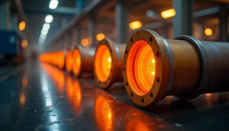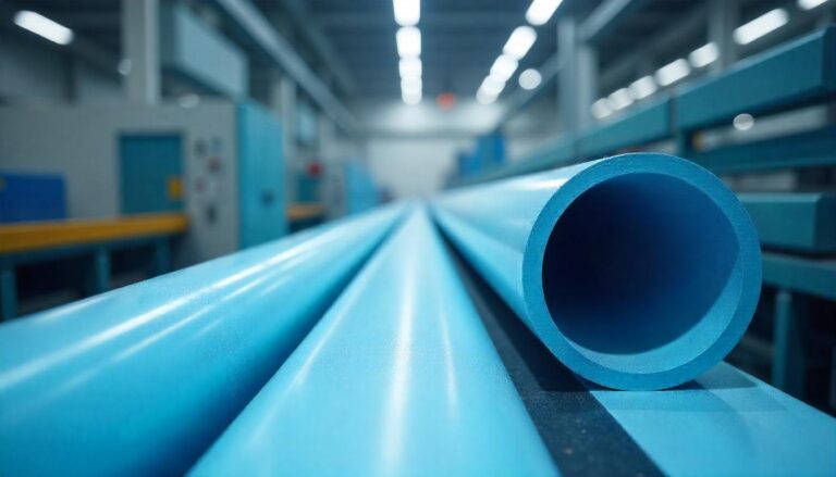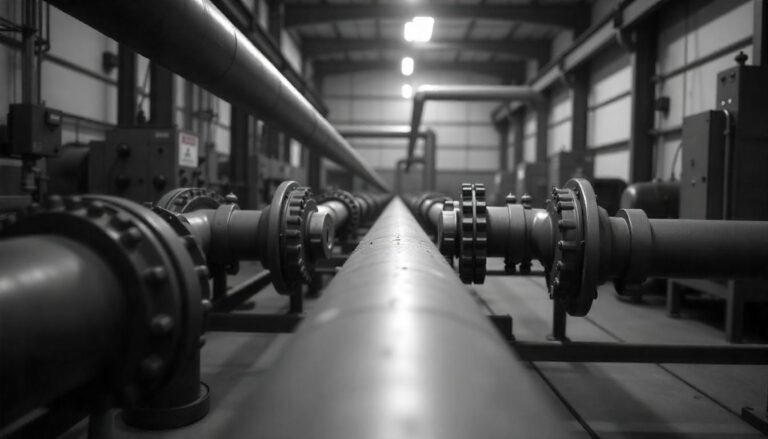
![Fire Water piping system]](https://srjpipingindia.com/wp-content/uploads/2019/11/img-5-fps-300x225.jpg)
Fire safety is the primary concern of any business owner. Seemingly harmless objects or everyday actions may cause most fires. But they are truly fueled by negligence and indifference. Fires result in fatalities, bodily injuries, infrastructural damage, and financial losses. That is why it pays to have a fire protection system in place.
Any commercial or non-commercial entity is incomplete without a full-fledged Fire Protection System (FPS). The myriad benefits of an FPS outweigh the potential risks of operating a business without such a system.
But if you’re still hesitant to invest and secure your establishment from fires, here are some things that you should know about such as what exactly constitutes a fire protection system, how does it actually work, and what are the different types of systems available on the market.
What is a Fire Protection System?
Simply put, the main goal of a fire protection system is to detect a fire and douse the flames. This means that the functionality of any FPS must be based on this essential principle of early detection and instantaneous suppression of fire. The design of a fire protection system varies from building to building. In other words, the process of integrating a warehouse with an FPS is not the same as installing an FPS in office spaces. However, the basic components of a fire protection system must revolve around three key objectives: detection, notification, and suppression.
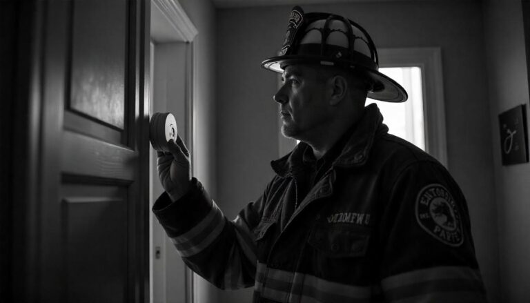
A fire detection system is a critical feature of any FPS since it is the first component to initiate the system, thereby resulting in the ultimate protection of the building and its occupants from a fire. These detection systems are available in various designs and can be manually activated, automated, or both. While fire alarm pull stations and water flow detectors are of the manual type, smoke detectors are sensor-activated detection systems that minimize the risk of false alarms.
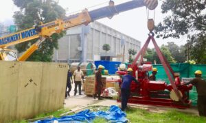
Fire Protection Systems in Bangalore:
After detecting a fire, the next objective of a fire protection system is to send out notifications about the fire and alert occupants to a potential emergency situation. This is where fire alarm systems come into the picture. A fire alarm system comprises sensory-based devices such as flashing lights or audible sirens. Nowadays, sophisticated fire alarm systems also communicate with emergency services by sending out a distress signal to the nearest fire station.
Usually, detection panels and fire alarm systems are packed into a single framework of fire protection systems. Additionally, some other components that can useful in the event of a fire are gas leak detection systems, emergency elevator systems, emergency door holders, etc.
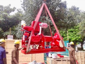
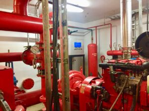
Why should you install a Fire Sprinkler System?
A fire sprinkler system is responsible for controlling, suppressing, and finally extinguishing the fire. When an integrated fire sprinkler system does its job properly and completely douses the fire, it not only safeguards workers (and protects valuables) but also helps firefighters avoid a potentially hazardous situation. The significance of investing in a fire sprinkler system for your company is demonstrated by past occurrences of fires in the workplace.
But it is not enough to just have a fire sprinkler system in place. In the past, most instances of a fire burning down an entire building have been a direct result of having improperly maintained or low-quality fire sprinkler systems. This goes to show that having a faulty fire sprinkler system is as dangerous as not having one at all.
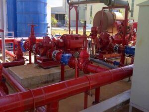
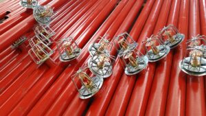
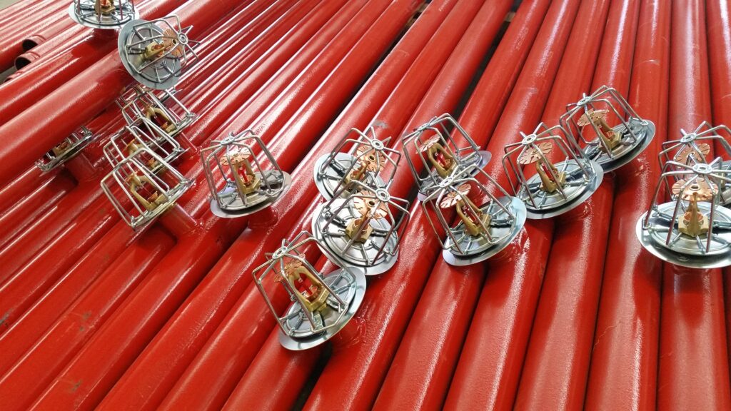
Fire sprinkler systems are generally categorized into two types: water-based sprinklers and foam-based sprinklers.
Water or wet pipe fire sprinkler systems are the most common type of systems installed in buildings. Wet pipe sprinklers are connected to a network of pipes that store cold and pressurized water. The sprinklers are fitted with a plug that is sensitive to heat. This heat-sensitive plug is made of an alloy commonly referred to as Wood’s metal. When the heat reaches a particular temperature, the Wood’s metal plug melts and water is released from the sprinklers. The flowing water hits the flower-shaped metal deflector and spreads out over a larger area.
Foam-based fire sprinkler systems are commonly fitted in hazardous areas where there is potential for chemical fires to occur. This includes locations such as oil rigs, airplane hangars, chemical factories, power plants, etc. This type of fire sprinkler system works in a similar fashion to the wet pipe sprinkler system. However, instead of water being discharged to put off the flames, a mixture of water and low-expansion foam flows out of the sprinklers in order to effectively extinguish the chemical fire. The foam is generally supplied from a separately located foam bladder tank.
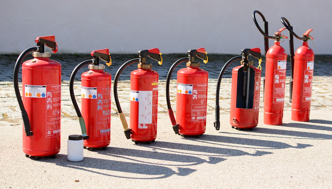
How do you choose the right fire extinguisher?
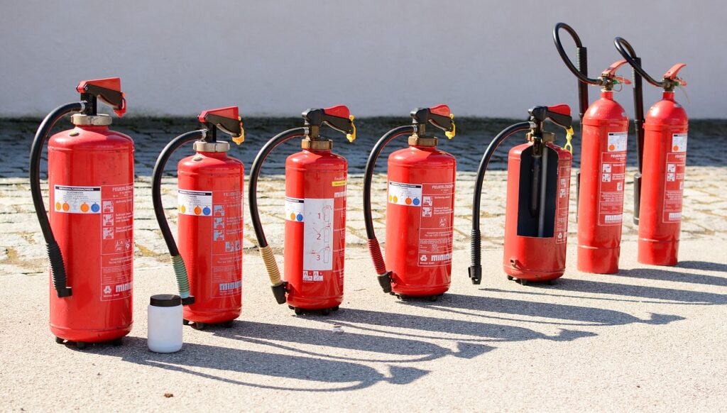
Is it still necessary to have fire extinguishers even if you’ve invested in a full-fledged fire protection system? The answer is yes. Fire extinguishers make up an integral part of a fire protection system. Often times, wall-mounted fire extinguishers go by unnoticed by the occupants of a building. But when a fire starts, this red cylinder makes the difference between a minor fire and total destruction.
Fire extinguishers can be used as the first firefighting measure taken in the event of a fire. You can think of them like a portable and easy-to-use fire protection system. Since most fires start out small before engulfing the whole area in flames, fire extinguishers are an indispensable component of a fire protection system. Best Fire Protection Systems in Bangalore: SRJ Piping India uses the size and contents of an extinguisher depending on the type of fire that could occur at the workplace.
While water and foam fire extinguishers are used to suppress non-electrical fires, carbon dioxide and other dry chemical extinguishers are used to tackle flammable liquid or electrical fires. The location of fire extinguishers also plays a key role in a fire protection system. Fire extinguishers must be mounted at a place that is easily accessible to everyone. Various color codes are used to designate the type of fire extinguisher. It is pivotal for all workers or employees to familiarize themselves with the process of operating a fire extinguisher.