SRJ Piping India company logo – leaders in fire protection, industrial piping, and heavy structural fabrication solutions

Top Software Tools for Piping Design and Fabrication in 2025

Top Software Tools for Piping Design and Fabrication in 2025

Table of Contents

Designing and fabricating safe, efficient, and compliant piping systems for industrial projects is crucial yet a complex task. Historically prone to manual errors and rework, this process is now revolutionized by advanced software.

For piping professionals in 2025, selecting the right software is key to optimizing workflows, enhancing collaboration, and ensuring project success. With advancements in 3D modeling, cloud, AI, and BIM, options are robust and specialized.

This guide will explore leading piping software, covering core functionalities, top contenders, emerging technologies, and the debate between free and paid options.

Specialized Piping Software Beyond General CAD

While general-purpose CAD software, such as standard AutoCAD, can be used for basic 2D drafting, the complexities of piping design and fabrication require far more specialized capabilities. Generic CAD tools simply aren’t built to handle these nuances efficiently or accurately.

Specialized piping design software, often part of larger plant design or BIM suites, provides functionalities crucial for modern workflows. These include:

  • Intelligent 3D Modeling: Not just lines and circles, but innovative components (pipes, fittings, valves, equipment) with embedded data (material, size, pressure rating). 
  • Automated Routing and Layout: Tools to assist in routing pipes while considering constraints, slopes, and clearances, significantly speeding up the design process.
  • Parametric Design: Easily modify pipe sizes, materials, or specifications, with the software automatically updating connected components and associated documentation.
  • Industry Standard Libraries: Access to pre-built libraries of standard components (flanges, elbows, tees, valves) from various manufacturers and according to international standards.
  • Code Compliance and Stress Analysis Integration: Tools that help ensure designs meet code requirements and facilitate seamless data transfer to stress analysis software.
  • Automated Drawing Generation: Automatically create deliverables, such as orthographic drawings, isometric drawings, and P&IDs, directly from the 3D model, reducing manual drafting time and errors.
  • Fabrication Deliverables: Generate spool drawings, cut lists, and welding lists essential for efficient off-site fabrication.
  • Clash Detection: Automatically identify spatial conflicts between pipes, structures, electrical trays, and other disciplines within the 3D model, preventing costly site rework.
  • Data Management and Collaboration: Centralized project data allows for better control, revision management, and collaboration among multidisciplinary teams.

Core Categories of Piping Software

Piping design and fabrication involve several distinct, yet interconnected, processes. Accordingly, the software landscape is segmented into tools that address these specific needs. While some comprehensive suites cover multiple categories, understanding these distinctions helps in evaluating individual tools:

  • 3D Plant/Piping Design Software: These are the core modeling tools used to create the intelligent 3D layout of pipes, equipment, and structures.
  • P&ID Software: Process and Instrumentation Diagrams (P&IDs) are schematic representations of process plants. 
  • Piping Stress Analysis Software: Crucial for ensuring the mechanical integrity of the piping system under various operating conditions.
  • Pipe Fabrication Software: Focuses on generating detailed drawings and data required for manufacturing pipe spools off-site, including cut lists, weld maps, and connection details. 
  • Data Management and Collaboration Platforms: Systems that manage the vast amount of data generated during design and fabrication, facilitate communication, track revisions, and provide a central source of truth for the project.
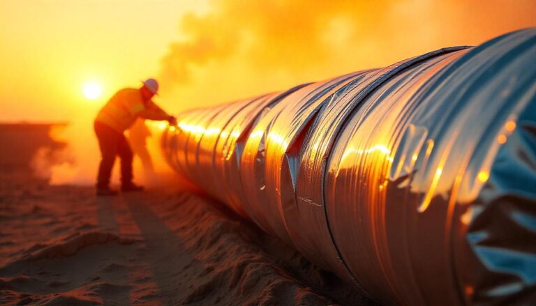
A bearded man wearing an orange safety vest and a yellow hard hat stands next to a large outdoor pipeline, looking down and typing on a laptop, with autumn trees and sunlight in the background.

Top 3D Modeling and Design Suites for 2025

These are the industry giants, offering comprehensive environments for laying out complex piping systems, equipment, and related structures in 3D.

Autodesk Plant 3D

A cornerstone in the plant design world, Autodesk Plant 3D, part of the AutoCAD suite, is widely used, leveraging the familiar AutoCAD platform. Its strength lies in intelligent P&IDs that link to the 3D model, extensive component libraries, automated drawing generation (orthographics, isometrics), and integrated clash detection.

Key Features: P&ID creation, 3D parametric modeling, spec-driven design, isometric generation, orthographic drawing generation, clash detection, BOM creation, integration with Navisworks for review.

Pros: Familiar interface for AutoCAD users, strong integration within the Autodesk ecosystem, widely adopted, and extensive community support.

Cons: Can be resource-intensive, advanced customization might require scripting (AutoLISP, NET), and the pricing model is subscription-based.

Aveva E3D Design (formerly PDMS/SmartPlant 3D)

Aveva E3D Design is a powerful, highly configurable 3D design software suite used extensively in large, complex plant projects, particularly in oil & gas, marine, and power industries. It’s known for its data-centric approach, robust capabilities in handling massive models, advanced clash management, and strong integration across the Aveva portfolio.

Key Features: Data-centric design, multidisciplinary modeling, advanced clash detection and management, automated drawing and report generation, extensive customization, and integration with laser scan data.

Pros: Highly scalable for massive projects, strong data integrity, powerful customization options, and industry-leading for complex plant environments.

Cons: Steeper learning curve, higher cost of entry and ownership, requires specialized expertise.

Bentley Systems OpenPlant

Bentley’s OpenPlant offers a comprehensive suite for plant design and operations, built on Bentley’s MicroStation platform. It provides intelligent 3D modeling, P&ID capabilities (OpenPlant PID), and integrates with Bentley’s other engineering analysis and asset performance tools. OpenPlant emphasizes interoperability and data management throughout the asset lifecycle. 

Key Features: Intelligent P&IDs and 3D modeling, spec-driven design, automated drawing generation, interoperability (including IFC and iModel), integration with Bentley’s broader portfolio (structural, electrical, analysis).

Pros: Strong data management focus, good interoperability, integrated suite covering multiple disciplines, suitable for large infrastructure projects.

Cons: Implementation and management can be complex, and the pricing model varies based on modules and usage.

Other Notable Mentions

While Autodesk, Aveva, and Bentley dominate the high-end market, other tools serve specific niches or offer alternative approaches:

  • Hexagon PPM (Intergraph) CADWorx: Often built on AutoCAD, offering intelligent plant design capabilities, particularly popular for smaller to medium-sized projects due to its ease of use and affordability relative to the top-tier suites. 
  • Dassault Systèmes CATIA: While primarily known for product design, CATIA also has applications in process plant design for specific industries, particularly where complex shapes and manufacturing integration are crucial.
  • SolidWorks (Dassault Systèmes): Primarily a mechanical design tool, but includes SolidWorks Routing for basic pipe, tube, and hose routing, suitable for smaller, less complex piping systems integrated within mechanical assemblies.
  • Bocad (Steel and Piping): Another tool focusing on detailed steel structure and piping design, often used in fabrication-driven workflows.

Piping Stress Analysis Software

Designing a piping system is more than just routing; it’s ensuring the system can withstand internal pressure, temperature changes, weight of contents and insulation, wind, seismic events, and other forces without failing or causing undue stress on connected equipment. 

Hexagon PPM (Intergraph) CAESAR II

CAESAR II is arguably the most widely used piping stress analysis software globally. It enables engineers to accurately analyze piping systems under various loads, verify compliance with numerous international codes and standards, and identify potential stress points or support issues before construction begins.

Key Features: Static and dynamic analysis, comprehensive code database, various load cases, spring hanger design, buried pipe analysis, and equipment nozzle load checking.

Pros: Industry standard, extensive code support, powerful analysis capabilities, good reporting features, integrates with many 3D design tools (including Plant 3D and CADWorx).

Cons: Requires specialized knowledge to operate correctly, and the user interface can feel dated compared to modern software.

Bentley Systems AutoPIPE

AutoPIPE is another leading piping stress analysis tool offered by Bentley. It provides similar capabilities to CAESAR II, focusing on static and dynamic analysis, code compliance checks, and integration with various CAD platforms, including Bentley’s OpenPlant and third-party tools such as Plant 3D. 

Key Features: Static and dynamic analysis, wide range of supported codes, load case generator, hanger design, buried pipe analysis, intuitive interface, integration capabilities.

Pros: User-friendly interface, seamless integration with the Bentley ecosystem and third-party tools, and comprehensive analysis features.

Cons: Advanced analyses can be complex, and licensing may be tied to Bentley’s broader suite of products.

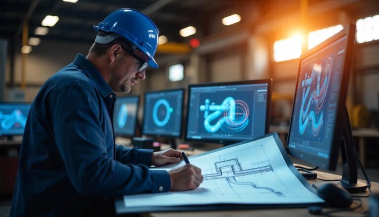
A profile shot of an engineer or designer wearing a blue hard hat, intently sketching on a blueprint while surrounded by multiple computer monitors displaying abstract industrial designs in a workshop setting with warm light.

Software for Pipe Fabrication and BIM Integration

Getting the design modeled in 3D is only the first step towards construction. Fabrication involves cutting, welding, and assembling pipe sections (spools) off-site before transport to the site for erection. Software plays a crucial role in streamlining this process, ensuring accuracy, and minimizing waste. 

BIM Software for Pipe Fabrication

While not exclusively focused on piping tools, BIM platforms like Autodesk Revit are central to fabrication workflows, particularly in the MEP (Mechanical, Electrical, Plumbing) sector. Revit enables modeling piping systems with fabrication-level detail using specialized content libraries (e.g., ITM content).

How BIM Supports Fabrication:

  • Detailed Modeling: Model piping systems using manufacturer-specific content at a higher Level of Detail (LOD), reflecting how components will be fabricated and installed.
  • Fabrication Spooling: Tools within BIM software (or connected plugins) allow designers to break down the overall piping model into buildable spools, complete with dimensions, welds, and component lists.
  • Automated Deliverables: Generate spool sheets, cut lists, BOMs, and NC (Numerical Control) data for automated cutting and welding machines directly from the detailed model.
  • Clash Detection: Ensure fabrication spools fit together and don’t clash with other building elements or services.

Specialized Fabrication Software

Some software tools are specifically designed for the fabrication shop, working with data from 3D design tools or BIM platforms.

  • Autodesk Fabrication CADmep/ESTmep/CAMduct: A suite of tools widely used in MEP fabrication. 
  • Stratus (mentioned in research): Stratus is a fabrication-focused platform, often integrating with BIM workflows (like Revit) to manage the fabrication process, from detailing and spooling to production tracking and logistics. 
  • Various Vendor-Specific Tools: Many pipe fitting, valve, or support manufacturers offer their software or plugins to integrate their specific products and fabrication methods into design and fabrication workflows.

The Rise of Cloud, Mobile, and Plugins in 2025

Beyond the core design and analysis packages, several trends are enhancing the flexibility and power of piping software, including cloud computing, mobile access, and specialized plugins. These areas were identified as white space opportunities in the competitor analysis.

Cloud Piping Software 2025

Cloud-based platforms and software-as-a-service (SaaS) offerings are becoming more prevalent. While full-featured 3D modeling in the cloud is still evolving due to computational demands, cloud platforms excel in data management, collaboration, and project review.

Benefits of Cloud:

  • Enhanced Collaboration: Teams in different locations can access and work on the same project data in real-time.
  • Improved Accessibility: Access project information from anywhere with an internet connection.
  • Centralized Data: A single source of truth reduces version control issues.
  • Reduced IT Overhead: No need for heavy investment in on-premise servers and infrastructure.
  • Scalability: Easily scale resources up or down based on project needs.

Mobile Piping Apps 2025

Mobile applications bring project data and some functionalities into the field. While you won’t be doing complex 3D routing on a phone, mobile apps are invaluable for:

  • Model Viewing: Review 3D models on site for visualization and understanding spatial relationships.
  • Data Access: Access component information, documentation, and installation details while in the field.
  • Progress Tracking: Update installation status, take photos, and link them to specific model elements.
  • Issue Management: Report clashes, errors, or site conditions directly from the field, linking them back to the central project data.
  • Collaboration: Communicate with the office or fabrication shop from the construction site.

Piping Design Plugins 2025

Plugins and add-ons extend the capabilities of core design software. They often provide specialized functionality that might not be included in the base package or offer enhanced workflows for specific tasks.

Examples:

  • Plugins for automated isometric drawing enhancements.
  • Tools for specialized material take-offs or cost estimation links (tying into the estimating software theme).
  • Connectors to specific stress analysis programs.
  • Add-ons for generating more detailed fabrication data.
  • Tools for importing/exporting data in specific formats (e.g., for welding management software).
  • Libraries of specialized components or equipment not found in the standard software catalog.
A close-up, dynamic shot of a dark industrial pipe adorned with glowing neon-like designs in red and blue, with bright orange sparks or particles suspended around it, and blurred figures in the background.

Free vs. Paid Piping Software in 2025

The question of the budget is always relevant. While professional-grade piping design and fabrication software typically requires a significant investment, free or lower-cost options are available. 

Paid Software (Professional Suites)

Examples: Autodesk Plant 3D, Aveva E3D Design, Bentley OpenPlant, Hexagon CADWorx, CAESAR II, AutoPIPE.

Cost: Can range from a few thousand dollars per year per license (for mid-range tools) to tens of thousands (or more) per year per license for high-end suites, plus potential costs for implementation, training, and support.

Best suited for: Professional engineering firms, EPC contractors, fabrication shops, and asset owners managing extensive plant infrastructure. Projects requiring accuracy, efficiency, scalability, and adherence to industry codes and standards.

Free/Open-Source or Low-Cost Software

Examples include FreeCAD (with piping workbenches), DraftSight (for 2D drafting, although it now has paid versions), and basic CAD tools with limited piping features. Some vendors offer viewers or limited-functionality versions for free.

Cost: Free to use, or a low one-time purchase or subscription cost.

Best For: Educational purposes, small-scale or conceptual work, individuals learning basics, elementary projects where code compliance is minimal or managed manually.

The Value Proposition

For professional use in 2025, relying solely on free or low-cost generic tools for complex piping projects is highly risky and inefficient. Many vendors offer trial versions or educational licenses, which can be a good way to evaluate capabilities before committing financially. Consider the total cost of ownership, including potential rework costs from errors caused by inadequate tools, when making the decision.

Conclusion

Piping design and fabrication in 2025 rely heavily on robust, integrated software tools, such as Autodesk Plant 3D, Aveva E3D Design, and Bentley OpenPlant, for 3D modeling, as well as CAESAR II and AutoPIPE for analysis. These specialized tools, far beyond general CAD, offer accuracy, efficiency, and collaboration, crucial for complex projects.

Strategic software selection involves assessing project needs, team expertise, budget, and workflow integration to ensure optimal outcomes. While free options exist, professional-grade software is vital for accuracy, efficiency, and compliance in industrial projects.

Leading firms must stay updated on software advancements, prioritizing tools that scale with project complexity, support industry standards, and integrate with cloud and AI. Investing in these digital, data-driven, and collaborative platforms is essential for future success in piping design and fabrication.

In closing, leveraging advanced software tools like AutoCAD Plant 3DCADWorx, and Smart 3D is no longer optional—it’s critical for achieving precision, efficiency, and compliance in modern piping design and fabrication. As we approach 2025, integrating AI-driven analytics, cloud collaboration, and BIM interoperability will redefine project success. For deeper dives into technology’s impact, explore our insights on structural fabrication trends and innovative piping solutions. Industry benchmarks from MECS Engineering and PiperCADD further illuminate best practices for tool selection and implementation.

Key Links:

  1. Role of Technology in Structural Fabrication

  2. Piping QA/QC Standards

Key Resources:

  1. Piping Design Checklist Guide

  2. Data Pipeline Platforms Analysis

Not Sure Which Piping Software Suits Your Project?

SRJ Piping India helps you select the best piping tools and material strategies tailored to your plant’s complexity, fabrication needs, and compliance standards.

Industrial Steel Structure Disasters: How to Prevent Costly Collapses

Industrial Steel Structure Disasters: How to Prevent Costly Collapses

Table of Contents

Did you know that structural failures in industrial settings lead to billions of dollars in damages and countless injuries each year? Safety in industrial operations, particularly concerning steel structures, is paramount. This comprehensive safety guide delivers critical, actionable protocols essential for preventing costly collapses, protecting personnel, and ensuring regulatory compliance. 

You will learn how to identify potential hazards, implement robust maintenance programs, and adhere to the highest safety standards, transforming your approach to structural integrity and overall workplace safety.

Understanding Industrial Steel Structure Regulations

Numerous regulatory bodies and standards govern the design, construction, maintenance, and inspection of steel structures. Key players include OSHA (Occupational Safety and Health Administration), which sets and enforces workplace safety standards; ANSI (American National Standards Institute), which develops voluntary consensus standards; and local building codes, which vary by jurisdiction. 

Specific standards, such as those published by the AISC (American Institute of Steel Construction) and AWS (American Welding Society), provide detailed guidelines for steel fabrication, erection, and welding.

Non-compliance can lead to severe consequences, including hefty fines, legal liabilities, project delays, and, most importantly, loss of life. A proactive approach to compliance, involving regular audits, training, and adherence to best practices, is crucial for maintaining a safe operating environment.

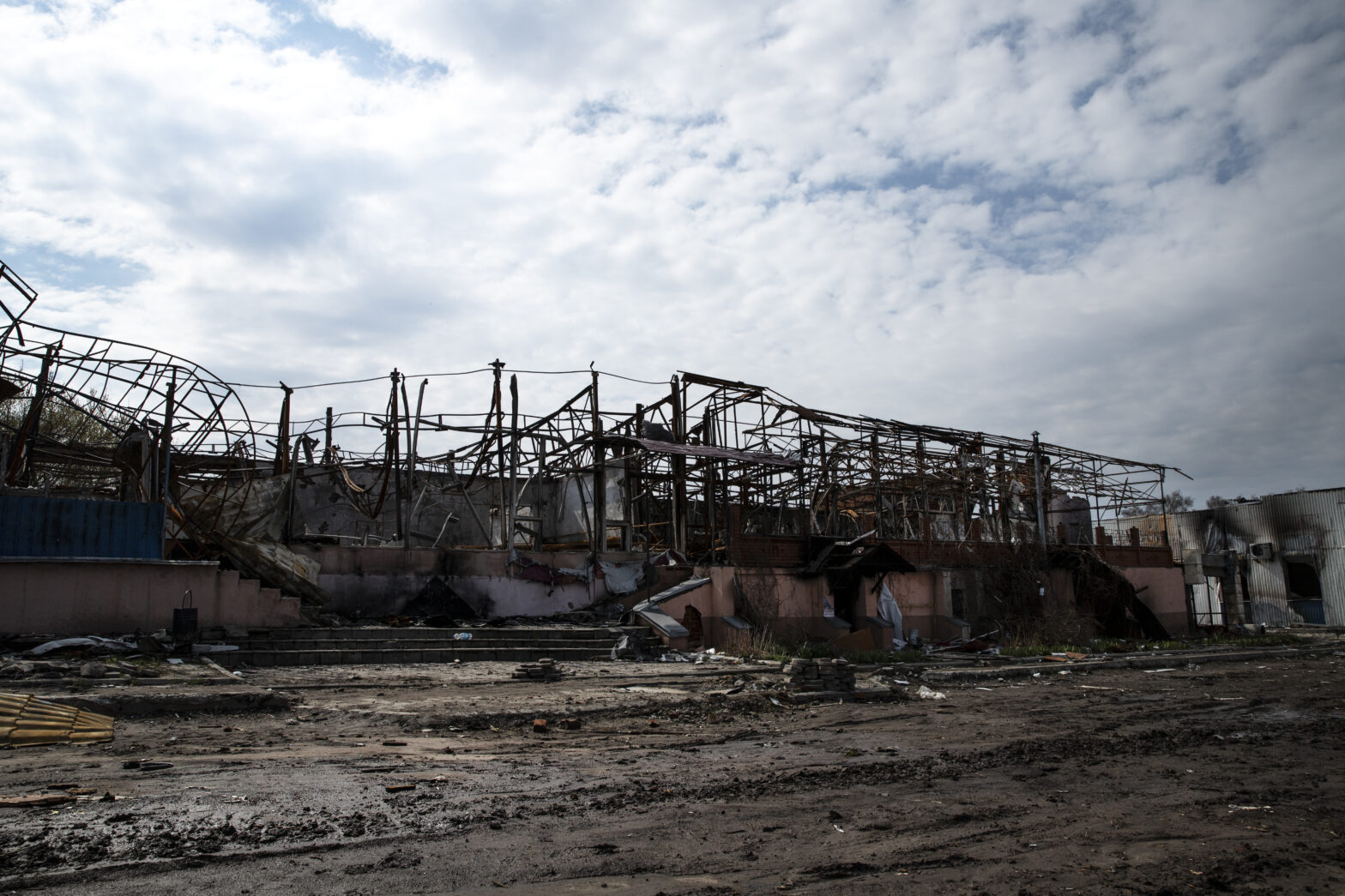
"Abandoned industrial facility with damaged steel structures and dim lighting"

Steel Structure Design Safety Protocols

Proper design is the foundation of structural safety. Design flaws are a significant contributor to the collapse of steel structures. The design phase must account for all potential loads, including dead loads (the weight of the structure itself), live loads (occupancy and equipment), environmental loads (wind, snow, and seismic activity), and dynamic loads (vibration and impact).

A detailed structural analysis, utilizing sophisticated software and considering all potential failure modes, is essential. Redundancy should be built into the design, providing alternative load paths in case of component failure. Connections, often the weakest points in a structure, must be designed with meticulous attention to detail.

Material Selection and Quality Control Safety Protocols

The quality of the steel used in construction has a direct impact on the structural integrity. Specify steel grades that meet or exceed required standards, ensuring they possess the necessary strength, ductility, and weldability.

Implement a rigorous quality control program that includes material testing, inspection of mill certificates, and verification of compliance with specifications. Conduct regular audits of suppliers to ensure they adhere to quality standards. Traceability of materials, from the mill to the final installation, is crucial for identifying and addressing potential defects.

Welding and Fabrication Safety Protocols

Welding is a critical process in steel structure construction, and welding failures can have catastrophic consequences. Employ certified welders who are proficient in the specific welding techniques required for the project.

Adhere strictly to welding procedures that comply with American Welding Society (AWS) standards. Ensure proper joint preparation, welding parameters, and post-weld inspection. Non-destructive testing (NDT) methods, such as ultrasonic testing and radiographic testing, should be used to detect weld defects. Visual inspection alone is insufficient.

Erection and Assembly Safety Protocols

The erection and assembly phase presents significant safety challenges. Develop a detailed erection plan that addresses lifting procedures, temporary bracing, and worker safety.

Use qualified riggers and crane operators. Inspect all lifting equipment before each use. Ensure that workers are adequately trained in safe erection practices. Implement fall protection measures, such as safety harnesses and nets, to prevent falls from height.

Corrosion Prevention Safety Protocols

Corrosion is a significant threat to steel structures, weakening the material and leading to eventual failure. Implement a comprehensive corrosion prevention program that includes protective coatings, cathodic protection, and regular inspections to ensure optimal safety and reliability.

Select coatings appropriate for the environment and ensure proper surface preparation before application. Regularly inspect coatings for damage and repair as needed. Consider using corrosion-resistant alloys in environments with corrosive conditions.

Fire Protection Safety Protocols

Steel loses strength at high temperatures, making fire protection a critical consideration. Apply fire-resistant materials, such as intumescent coatings or concrete encasement, to protect steel members from fire damage.

Design fire suppression systems, such as sprinklers, to quickly extinguish fires. Develop and implement a comprehensive fire safety plan that includes evacuation procedures and fire drills. Regularly inspect and maintain fire protection systems.

Seismic Design Safety Protocols

In seismically active areas, steel structures must be designed to withstand the forces of earthquakes. Incorporate seismic design principles into the structural design, following relevant building codes and standards.

Use ductile materials and connections that can absorb energy during an earthquake. Conduct a seismic risk assessment to identify potential vulnerabilities and implement mitigation measures. Regularly inspect structures for earthquake damage after seismic events.

Overloading Prevention Safety Protocols

Overloading can cause catastrophic structural failure. Establish clear load limits for the structure and implement measures to prevent overloading. Monitor loads regularly and ensure they do not exceed design limits.

Provide training to personnel on load limits and the consequences of exceeding load limits. Implement load monitoring systems, such as strain gauges, to detect overloading in real-time. Regularly inspect structures for signs of overloading, such as excessive deflection or cracking.

Preventive Maintenance for Steel Structures

Regular inspection and maintenance are crucial for identifying and addressing potential problems before they lead to failure. Develop a comprehensive preventive maintenance program that includes regular inspections, thorough cleaning, and timely repairs.

Train personnel to recognize signs of deterioration, including corrosion, cracking, and deformation. Keep detailed records of inspections and maintenance activities. Address any identified problems promptly.

Steel Structure Inspection Quality Checklist

A comprehensive inspection checklist is an essential tool for ensuring structural integrity. The checklist should include items such as:

  • Visual inspection for corrosion, cracking, and deformation
  • Inspection of welds for defects
  • Inspection of connections for loose or missing fasteners
  • Inspection of coatings for damage
  • Verification of load limits
  • Assessment of environmental factors
  • Review of maintenance records

The checklist should be updated regularly to reflect changes in the structure or operating conditions.

Environmental Factors Safety Protocols

Environmental factors, such as temperature, humidity, and chemical exposure, can significantly impact the lifespan and integrity of steel structures. Consider these factors during the design phase and implement measures to mitigate their effects.

Use corrosion-resistant materials in harsh environments. Provide adequate ventilation to reduce humidity. Protect steel structures from chemical exposure. Regularly inspect structures for environmental damage.

Human Error and Operational Safety Protocols

Human error is a contributing factor in many structural failures. Implement measures to reduce the risk of human error, such as providing adequate training, establishing clear procedures, and promoting a safety culture.

Ensure that personnel are aware of potential hazards and know how to respond to emergencies. Encourage open communication and reporting of safety concerns. Conduct regular safety audits to identify possible weaknesses in the system.

Case Studies of Steel Structure Collapses

Analyzing past collapses can provide valuable lessons for preventing future incidents. Documented case studies reveal common causes, such as design flaws, material defects, inadequate maintenance, and human error.

Understanding the root causes of these failures can help organizations identify potential vulnerabilities in their structures and implement corrective measures. Share case studies with personnel to raise awareness of the possible consequences of neglecting safety protocols.

Emergency Response and Evacuation Plans

Despite the best efforts at prevention, structural failures can still occur. Develop and implement a comprehensive emergency response and evacuation plan to minimize the impact of a collapse.

The plan should include procedures for notifying emergency services, evacuating personnel, and securing the site in the event of an emergency. Conduct regular drills to ensure that personnel are familiar with the plan. Provide training to personnel on how to respond to different types of emergencies.

Risk Assessment & Hazard Identification

Hazard identification involves systematically identifying potential dangers in the industrial environment. This includes evaluating all aspects of the operation, from the materials used to the processes employed and the equipment involved. Conduct regular walk-throughs, review safety data sheets (SDS), and analyze accident reports to uncover potential hazards.

Risk assessment involves evaluating the likelihood and severity of potential hazards. Utilize techniques such as Failure Mode and Effects Analysis (FMEA) and Hazard and Operability (HAZOP) studies to assess risks thoroughly. Develop a risk assessment matrix to prioritize hazards based on their potential impact and likelihood of occurrence. Implement mitigation strategies to reduce or eliminate identified risks.

Safety Training & Culture Development

Implementing robust safety protocols is not merely a regulatory requirement; it is a fundamental responsibility. By prioritizing safety in steel structure design, construction, maintenance, and operation, organizations can prevent costly collapses, protect their workforce, and ensure the long-term sustainability of their operations. A strong safety culture, coupled with diligent adherence to best practices, is the key to creating a safe and productive industrial environment.

Request a comprehensive safety audit for your facility from SRJ Piping India and proactively safeguard your operations against potential disasters. Contact us for expert safety consultation and ensure your steel structures meet the highest safety standards.

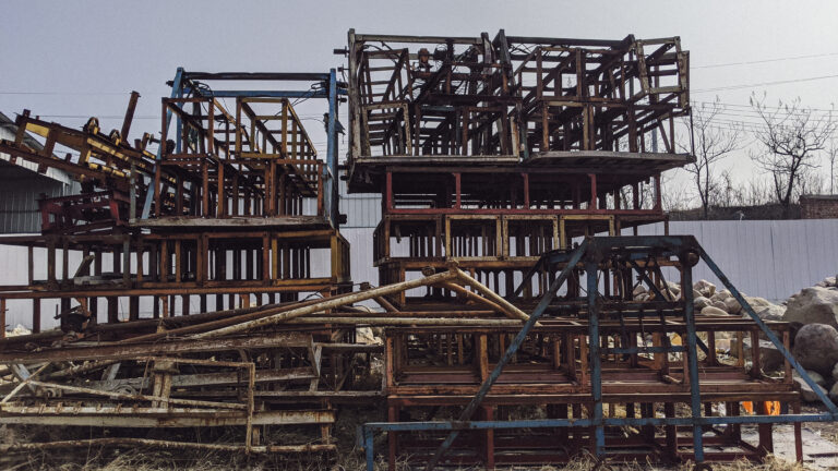
Stacked and rusted steel frameworks at a construction site under overcast sky

Conclusion

Successfully implementing cost-saving measures in pipe fabrication projects requires a holistic approach that focuses on efficiency and value at every stage. By systematically addressing these areas, you can unlock significant savings and improve the financial performance of your pipe fabrication projects. Begin your initial assessment today and pave the way for more cost-effective and successful outcomes.

Do you need expert assistance, or are you looking for a fabrication partner that prioritizes cost optimization? Discover SRJ Piping India’s solutions next.

Worried About Structural Failures in Your Facility?

Get a professional safety audit to prevent collapses, ensure compliance, and secure your steel structures for the long term.

Best Practices for Pipe Fabrication in High-Pressure Systems

Best Practices for Pipe Fabrication in High-Pressure Systems

Table of Contents

Building high-pressure piping systems for industrial facilities is a complex, critical task with severe consequences if overlooked. Failures can be catastrophic, leading to environmental damage, property loss, and fatalities. Ensuring the integrity, reliability, and safety of these systems demands meticulous planning, expert execution, and stringent quality control, along with a deep understanding of materials, engineering, and welding.

This guide will demystify high-pressure pipe fabrication, outlining key stages from design and material selection to welding, inspection, testing, and commissioning. By the end, you’ll have a clear roadmap to confidently build high-pressure piping systems that meet the highest safety and performance standards.

Step-by-Step Guide to High-Pressure Pipe Fabrication

Fabricating piping for high-pressure applications is a multi-stage process that requires precision, adherence to standards, and rigorous quality control at every stage. Rushing or skipping steps is not an option. Here are the core stages involved:

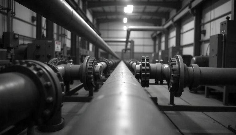
Black and white view of an industrial pipe system in a manufacturing facility, showing multiple bolted flanges in a symmetrical layout.

Detailed Planning, Review, and Material Verification

Before any physical work begins, a thorough review of the design documents, specifications, and procedures is essential. This is where you ensure everyone involved understands the project’s requirements and constraints.

What to Do:

  • Review and cross-reference all relevant drawings (P&IDs, Isometrics, GAs) against the material specifications and design basis. 
  • Hold a pre-fabrication meeting with the engineering, fabrication, welding, and quality control teams to discuss the scope, critical joints, special requirements (such as heat treatment), and the inspection plan.
  • Verify that all required materials (pipes, fittings, flanges, etc.) have arrived on-site, match the specifications, and are accompanied by the necessary Mill Test Reports (MTRs) or Certificates of Compliance. 
  • Implement a material traceability system. Mark each piece of material with a unique identifier that links it back to its MTR. 
  • Confirm that all required WPS, PQR, and Welder Performance Qualifications (WPQs) are available, approved, and cover the specific materials and welding processes to be used.
  • Review the fabrication sequence and lifting plans, especially for large or complex spools.

Why it Matters:

This initial review phase is your opportunity to catch potential problems on paper before they become costly mistakes in the workshop. Verifying materials ensures that the system will have the properties required to withstand high pressure and temperature. Confirming procedures and qualifications ensures that critical welding work is performed by competent individuals using approved methods.

Accurate Cutting and Edge Preparation

Once materials are verified, they are cut to the required lengths according to the spool drawings. Just as critical as cutting is the preparation of the edges that will be joined, usually by welding.

What to Do:

  • Lay out the pipe lengths precisely according to the cutting list derived from the isometric drawings. Double-check measurements.
  • Use the appropriate cutting method based on the material and the required accuracy. For high-pressure piping, thermal cutting methods like plasma or oxy-acetylene may be used for rough cuts on certain materials. 
  • Most high-pressure butt welds require a specific bevel angle (often 30-37.5 degrees) to create a groove for welding. This is typically done using bevelling machines (manual or automated) or grinders. 
  • Ensure the bevel angle, root face (the slight flat edge at the bottom of the bevel), and root gap (the space between two pipes to be joined) are precise according to the WPS. 
  • Maintain material traceability by transferring heat numbers or unique identifiers from the cutoff piece to the new, smaller piece.

Why it Matters:

Accurate cutting ensures the spools fit together correctly during assembly and installation. Proper edge preparation is fundamental to achieving a sound, full-penetration weld. Incorrect bevel angles, root faces, or gaps can lead to weld defects such as lack of fusion, lack of penetration, or excessive distortion, all of which can compromise the strength and integrity needed for high-pressure containment.

Fit-Up and Alignment

Fit-up is the process of bringing pipe pieces, fittings, and flanges together in preparation for welding. Correct fit-up is crucial for maintaining dimensional accuracy and enabling high-quality welds.

What to Do:

  • Position pipe sections and components (such as fittings and flanges) according to the spool drawings. 
  • Align the components carefully, ensuring that the root gap and internal alignment are within the tolerances specified by the WPS and applicable codes. 
  • Use temporary attachments (tack welds or bridge tacks) to hold the components in place once aligned. 
  • Verify the overall dimensions and geometry of the assembled spool against the drawings before committing to the full weld. 
  • Clean the joint area thoroughly before welding, removing any grease, oil, paint, or rust from the surface.

Why it Matters:

Accurate fit-up is crucial for achieving the correct geometry of the pipe spool and ensuring it connects properly to adjacent sections during installation. More importantly, proper fit-up (especially alignment and root gap) directly influences the welder’s ability to achieve a high-quality root pass, which is the foundation of a strong weld in high-pressure applications.

The Critical Process of Welding

Welding is arguably the most critical step in high-pressure pipe fabrication. A defective weld can be a catastrophic failure point. This stage requires highly skilled personnel, strict adherence to procedures, and careful control of welding parameters.

What to Do:

  • Ensure the qualified welder is using the correct Welding Procedure Specification (WPS) for the specific material and joint type.
  • Apply preheating if required by the WPS, using calibrated heating equipment (e.g., heating pads, induction heaters). 
  • Perform the root pass using the specified welding process (e.g., GTAW/TIG is often preferred for root passes in high-pressure piping due to its control and ability to produce high-quality, clean welds). 
  • Clean the root pass thoroughly before depositing subsequent weld layers (fill passes and cap pass). 
  • The deposit filler passes the specified welding process and filler material requirements. Follow the specified interpass temperature as per the WPS.
  • Complete the weld with a cap pass, ensuring proper tie-in to the bevel edges and sufficient reinforcement (weld crown height) as specified by the code and the Welding Procedure Specification (WPS).
  • Apply post-weld heat treatment (PWHT) as required by the code, material, or welding procedure specification (WPS). 
  • Visually inspect the completed weld immediately after it cools (or after PWHT if applicable) for surface defects such as cracks, porosity, undercut, or insufficient reinforcement.

Why it Matters:

Welding joins the components together to create a continuous pressure boundary. High-pressure systems subject welds to immense stress. Any defect within the weld or the adjacent heat-affected zone can act as a stress concentration point, leading to crack initiation and potentially catastrophic failure under operating conditions.

Rigorous Inspection and Non-Destructive Testing (NDT)

Once welding is complete, the fabricated spool must undergo thorough inspection and testing to verify its integrity. For high-pressure systems, this goes beyond visual checks.

What to Do:

  • Perform a detailed visual inspection of all welds. Check for surface imperfections, profile issues, and signs of cracking.
  • Conduct dimensional checks on the completed spool to ensure it matches the drawings, including length, flange face-to-face dimensions, nozzle and branch locations, and alignment.
  • Apply Non-Destructive Testing (NDT) methods as required by the code, work procedure specification (WPS), or quality control (QC) plan. Standard NDT methods for high-pressure welds include:
  1. Radiography Testing (RT)
  2. Ultrasonic Testing (UT)
  3. Magnetic Particle Testing (MT) or Liquid Penetrant Testing (PT)

Why it Matters:

NDT methods allow inspectors to “see” inside the weld or examine the surface for defects that are not visible externally. Finding and repairing defects during fabrication is significantly cheaper and safer than dealing with a leak or failure after the system is operational.

Pressure Testing (Hydrostatic or Pneumatic)

The final, definitive test of the fabricated spool’s ability to withstand pressure is the hydrostatic or pneumatic test. This is a critical safety measure that must be performed before the system goes into service.

What to Do:

  • Prepare the spool for testing. This involves temporarily capping off open ends, installing test blinds on flanges, and adding vents and pressure gauge connections. 
  • Fill the spool with the test medium. For hydrostatic testing, this is typically water. Ensure the system is filled, and all air is vented. 
  • Slowly increase the pressure in the spool to the required test pressure, as specified by the code (e.g., 1.5 times the design pressure for ASME B31.3 hydrostatic test, adjusted for temperature).
  • Hold the test pressure for the specified duration (e.g., typically 10 minutes for visible leak checks, but this duration may be longer).
  • During the hold time, visually inspect the spool, paying close attention to welds, flanges, fittings, and any other connections to check for leaks. 
  • After the hold time, slowly depressurize the spool.
  • Thoroughly drain and dry the spool after hydrostatic testing to prevent internal corrosion, especially if the material is susceptible to it.
  • Document the test pressure, hold time, test medium temperature, and result (pass/fail) in a pressure test report (pressure piping documentation).

Why it Matters:

The pressure test is a final, overall check of the entire fabricated spool’s integrity, including all welds, joints, and components. It simulates stresses exceeding normal operating conditions to prove the system can safely contain the design pressure. Successfully passing a pressure test is a mandatory requirement before a high-pressure system can be put into service.

Surface Treatment and Preservation

After successful pressure testing, the spool may require surface treatment, such as painting or coating, for corrosion protection, identification, or aesthetic reasons.

What to Do:

  • Clean the external surface of the spool thoroughly to remove any grease, oil, rust, or welding spatter. Surface preparation methods (like sandblasting) must be appropriate for the material and the intended coating system.
  • Apply the specified coating system (e.g., primer and topcoat) according to the manufacturer’s instructions and project specifications. 
  • Mark the spool with its unique identification number, service designation, flow direction, and any other required information as per project standards. 
  • Apply internal preservation if the spool will be stored for an extended period before installation, especially for materials susceptible to internal corrosion. 
  • Protect flanged faces and bevelled ends with covers or protectors to prevent damage during handling, storage, and transportation.

Why it Matters:

Surface treatment protects the external surface of the pipe from corrosion and environmental degradation, extending the lifespan of the system. Proper marking ensures correct identification and orientation during installation, preventing costly errors. Preservation protects the internal surfaces from corrosion before the system is commissioned and filled with the process medium.

Documentation and Handover

The final, crucial step in the fabrication process is the compilation of all documentation and the formal handover of the completed spools.

What to Do:

  • Compile the Manufacturer’s Data Record (MDR) or Fabrication Dossier. 
  • Ensure all documentation is complete, accurate, signed, and reviewed by the quality control team. 
  • Package the fabricated spools appropriately for transportation, ensuring protection of vulnerable areas (like flange faces).
  • Formally hand over the fabricated spools and the complete documentation package to the client or the site construction team.

Why it Matters:

The documentation package provides a comprehensive history of the fabrication process, verifying that all requirements were met and demonstrating the system’s integrity. This dossier is essential for regulatory compliance, future maintenance, modifications, and troubleshooting. It serves as the birth certificate for the high-pressure system.

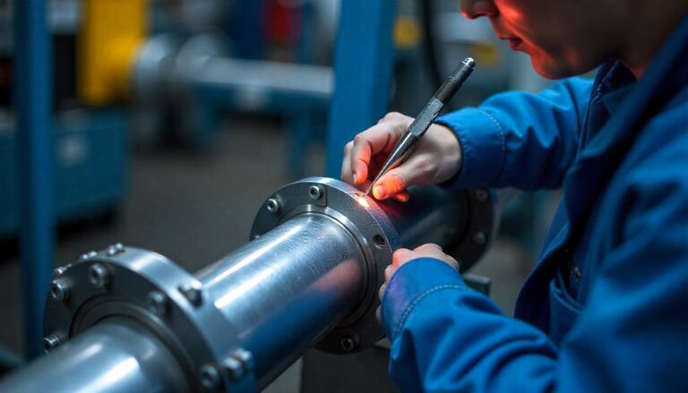
Technician marking a metal pipe flange for welding in an industrial fabrication workshop.

Conclusion

Fabricating high-pressure piping systems is a complex undertaking that demands meticulous planning, skilled execution, and unwavering commitment to quality and safety standards. It’s a process where the most minor oversight can have significant consequences, making attention to detail not just good practice, but an absolute necessity.

Building systems you can trust requires following these steps diligently, prioritizing safety above all else, and maintaining a sharp focus on quality at every stage. While challenges may arise, a structured approach and a commitment to best practices will guide you toward successful fabrication.

Begin your initial assessment and planning today and take the first step towards securing your facility’s high-pressure piping systems.

Need expert assistance in navigating the complexities of high-pressure pipe fabrication, ensuring compliance, or executing a critical project? Discover SRJ Piping India’s solutions next.

Need Expert Help With High-Pressure Pipe Fabrication?

Let SRJ Piping India guide you with proven techniques, certified welders, and cost-effective fabrication strategies that ensure safety and compliance—every time.

How to Unlock Significant Cost Savings in Industrial Pipe Fabrication

How to Unlock Significant Cost Savings in Industrial Pipe Fabrication

Table of Contents

Are you a project manager, facility owner, or engineer grappling with the rising costs of industrial pipe fabrication? Do budget overruns and unexpected expenses feel like an inevitable part of the process?

You’re not alone in facing these complex challenges. Balancing quality, compliance, and project timelines while keeping costs under control is a constant challenge in the world of industrial piping.

The good news? It doesn’t have to be this way. Significant savings are possible, often by implementing strategic approaches and leveraging modern techniques that go beyond simply finding the cheapest supplier.

By the end of this comprehensive guide, you’ll confidently know how to identify key cost drivers and implement proven strategies for cost-saving in pipe fabrication projects, ensuring both efficiency and financial health.

Guide to Cost Optimization in Pipe Fabrication

Reducing costs in pipe fabrication is a multi-faceted endeavor, requiring attention at every stage of the project lifecycle. Here’s a step-by-step approach to identify opportunities and implement effective saving strategies.

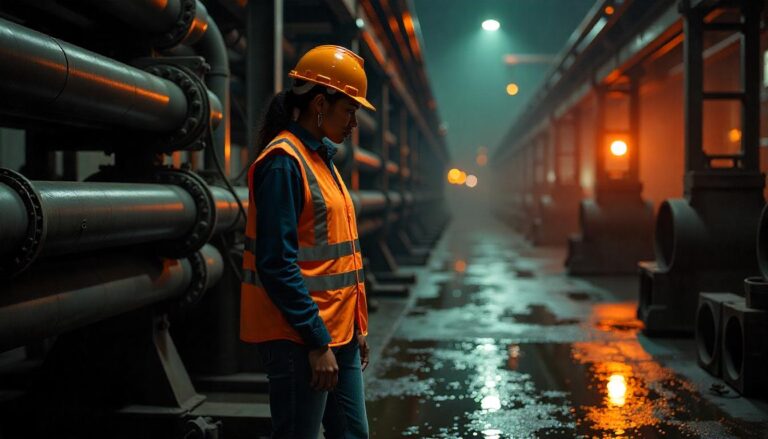
Female industrial worker wearing a hard hat and safety vest inspecting large metal pipes in a dimly lit factory with warm lighting.

Strategic Planning & Design Optimization Through Prefabrication

The most impactful cost savings often begin long before the first cut is made. Strategic planning and optimizing the design phase, particularly through the adoption of pipe prefabrication, can drastically reduce on-site labor, improve quality, and compress schedules.

What to do:

  • Identify Fabrication Candidates: Review blueprints with prefabrication in mind. Identify sections of piping that can be assembled into spools or modules off-site. 
  • Collaborate Early: Their expertise can help optimize spool breaks, minimize field welds, and design modules for efficient transport and installation.
  • Modular Design: For large or complex systems, explore modular construction where significant portions of the piping system, along with other equipment, are assembled into large modules in the shop.
  • Standardize Designs: Where possible, standardize pipe sizes, schedules, and component specifications across the project to leverage economies of scale in procurement and fabrication.

Why it matters:

Fabricating in a controlled shop environment yields higher welding quality due to improved positioning, controlled atmospheric conditions, and access to specialized equipment. This reduces rework, a significant cost driver. It also shifts labor from the often more expensive, less efficient, and safety-challenging field environment to a shop, reducing field hours.

Brilliant Material Selection & Procurement Strategies

Materials represent a significant portion of pipe fabrication costs. Making informed decisions about material types, specifications, and procurement can lead to substantial savings without compromising performance or compliance.

What to do:

  • Performance vs. Cost Analysis: Don’t automatically select the highest grade or most expensive material. 
  • Value Engineering: Work with engineering to explore alternative, less expensive materials or grades that are still suitable for the application. 
  • Optimize Cut Lists and Yield: Use advanced software or careful planning to optimize pipe cutting and minimize scrap. 
  • Bulk Purchasing: Buy materials in larger quantities when prices are favorable, if storage and inventory management are feasible.
  • Negotiate with Suppliers: Build strong relationships and negotiate pricing, payment terms, and delivery schedules with multiple qualified vendor management partners.
  • Spot Market vs. Contract: Understand market fluctuations and decide whether spot buying or long-term contracts offer better price stability and savings for specific materials.
  • Verify Material Certifications: Ensure all materials are accompanied by verifiable Mill Test Reports (MTRs) to prevent the use of incorrect or substandard materials, which can lead to costly rework or failures later.

Why it matters:

Selecting the right material for the job ensures the long-term integrity and safety of the piping system while avoiding unnecessary expenditure on over-specified components. Efficient procurement minimizes the direct cost of raw materials, and optimizing cut lists directly reduces waste, turning potential scrap into usable components. This directly impacts the overall cost-saving in pipe fabrication.

Optimizing the Fabrication Process: Focus on Welding and Bending

The core fabrication process involves cutting, fitting, beveling, bending, and welding. Each of these steps presents opportunities for cost optimization through efficiency improvements, technology adoption, and skilled execution.

What to do:

  • Choose the Right Welding Process: Select welding methods (e.g., TIG, MIG, SAW, FCAW) appropriate for the material, pipe size, schedule, and required quality. 
  • Minimize Arc-On Time: Reduce non-value-added activities such as fitting, grinding, and material handling to maximize actual welding time.
  • Optimize Weld Passes: Plan the number and size of weld passes to meet code requirements efficiently, minimizing excessive filler metal and labor.
  • Proper Training and Skill: Ensure welders are highly skilled and qualified for the specific procedures required. 
  • Leverage Automated Welding: Investigate and implement automation in pipe fabrication, particularly for repetitive welds. 
  • Optimize Bending vs. Fittings: Analyze the cost and feasibility of bending pipes versus using elbows and fittings to determine the most cost-effective approach. 
  • Use Advanced Cutting and Beveling Equipment: Automated cutting and beveling machines (like CNC plasma or oxy-fuel cutters) ensure precise fits, which reduces fitting time and improves weld quality.

Why it matters:

Efficient welding is crucial as it’s labor-intensive and heavily impacts quality. Reducing weld passes, minimizing rework through skilled welders, and leveraging automation directly lowers labor and consumable costs. Optimizing bending reduces the total number of welds and potential leak points, streamlining the pipe assembly process and saving on future inspection and repair costs.

Implementing Lean Inventory Management

Inventory management might seem less glamorous than fabrication, but inefficient practices can lead to substantial costs through tied-up capital, storage expenses, obsolescence, and project delays due to missing parts. Implementing lean principles is key to achieving inventory savings in pipe projects.

What to do:

  • Just-In-Time (JIT) Delivery: Coordinate material deliveries to arrive shortly before they are needed in the fabrication sequence. 
  • Accurate Forecasting: Develop precise material requirements based on the fabrication schedule to ensure timely and efficient production. 
  • Centralized Inventory Control: Implement a system to track all materials, including those received, consumed accurately, and in stock.
  • Minimize Safety Stock: While a small safety stock might be necessary for critical items, keep it as low as possible—high safety stock ties up capital and storage space.
  • Negotiate Supplier Lead Times: Work with suppliers to reduce lead times, enabling you to order materials closer to the time they are needed.
  • Return Unused Materials: Establish procedures for returning excess or unused materials to suppliers where feasible, or allocate them to future projects if appropriate.

Why it matters:

Excess inventory is a hidden cost. It requires storage space (which incurs costs), ties up working capital that could be utilized elsewhere, is susceptible to damage or degradation, and increases the risk of obsolescence. Efficient stock control ensures that materials are available when needed for the fabrication process, preventing costly delays and minimizing the financial burden of holding unnecessary stock.

Leveraging Automation & Technology

While touched upon in welding, automation in pipe fabrication extends to many other areas, offering significant potential for cost-saving in pipe fabrication by increasing efficiency, accuracy, and throughput, while reducing labor dependency and human error.

What to do:

  • Automated Cutting and Beveling: Utilize CNC pipe cutting machines that can precisely cut and bevel pipes according to digital models, ensuring perfect fit-ups and reducing manual labor.
  • Robotic Welding: Implement robotic systems for repetitive and standardized welding tasks, particularly for spools in the shop.
  • Automated Material Handling: Utilize cranes, conveyors, and robotic arms to move heavy pipes efficiently and spools within the fabrication facility, enhancing safety and productivity.
  • Fabrication Software: Implement advanced software for design (3D modeling), detailing, generating cut lists, managing inventory, scheduling, and tracking progress. 
  • Real-time Monitoring: Utilize sensors and data analytics to continuously monitor machine performance, material flow, and project progress in real-time. 
  • Digital Documentation: Move away from paper-based systems. Digital documentation of procedures, quality checks, and material certifications improves traceability and reduces administrative costs.

Why it matters:

Automation and technology streamline repetitive tasks, enhance precision, and accelerate the fabrication process. This leads to lower labor costs per fabricated unit, reduced material waste due to increased accuracy, and improved overall throughput. Digital tools enhance planning, execution, and tracking, minimizing errors and improving project control, which collectively contribute to overall fabrication optimization and cost reduction.

Enhancing Quality Control & Reducing Rework

Poor quality is costly. Reworking fabricated spools, repairing welds, or dealing with failures after installation can quickly erode project budgets. Implementing rigorous quality assurance protocols is a direct path to significant pipe QA cost savings.

What to do:

  • Establish Clear Quality Standards: Define and communicate stringent quality requirements based on applicable codes and project specifications.
  • Implement In-Process Inspections: Don’t wait until fabrication is complete to inspect. Conduct inspections at critical stages, such as after cutting, beveling, fitting, and before welding. 
  • Qualified Personnel: Ensure all welders, fitters, and inspectors are appropriately trained, competent, and certified.
  • Non-Destructive Testing (NDT): Utilize appropriate NDT methods (e.g., radiography, ultrasonic testing, magnetic particle testing, liquid penetrant testing) as required by codes and specifications to verify weld integrity.
  • Hydrostatic or Pneumatic Testing: Perform pressure testing on fabricated spools before they leave the shop to detect leaks early. 
  • Proper Material Traceability: Maintain meticulous records linking materials to specific spools and welds. This is crucial for quality checks and potential recalls.
  • Root Cause Analysis: When defects occur, conduct a thorough analysis to understand the root cause of the issue and implement corrective actions to prevent recurrence.

Why it matters:

Rework incurs costs in labor, materials, consumables, and schedule delays. Every weld repair or re-fabricated spool adds direct expense. By proactively identifying and preventing defects through robust quality control and in-process inspections, you minimize or eliminate costly rework, ensuring that resources are used efficiently. Finding issues in a controlled shop environment is significantly less expensive and faster than fixing them in the complex and often hazardous field environment.

Effective Project Management & Vendor Coordination

Even with optimized fabrication processes, poor project management and ineffective vendor coordination can lead to delays, miscommunication, and unexpected costs. Streamlined planning and strong relationships are vital for preventing pipe fabrication cost overruns.

What to do:

  • Detailed Project Scheduling: Develop a realistic and detailed project schedule for pipe fabrication that encompasses all phases, including engineering, procurement, fabrication, logistics, and installation. 
  • Integrated Planning: Ensure seamless data flow between design, procurement, and fabrication software systems to facilitate efficient project management. 
  • Proactive Risk Management: Identify potential risks early (e.g., material price fluctuations, supplier delays, weather impacts, labor shortages) and develop mitigation strategies.
  • Strong Vendor Relationships: Cultivate partnerships with reliable suppliers and subcontractors to ensure a stable supply chain. 
  • Performance Tracking: Monitor key performance indicators (KPIs) for fabrication progress, material consumption, welding efficiency, and quality results. 
  • Manage Scope Creep: Clearly define the project scope from the outset and implement a formal change management process to evaluate the cost and schedule impact of any requested changes before they are approved.

Why it matters:

Effective management acts as the conductor of the orchestra, ensuring all components of the complex pipe fabrication project work in harmony. Poor planning and coordination lead to wasted time, resources, and materials. Delays often incur penalties or escalate labor costs, directly contributing to budget overruns. Strong vendor relationships ensure the timely delivery of correct materials and services, preventing downtime in the fabrication shop or field.

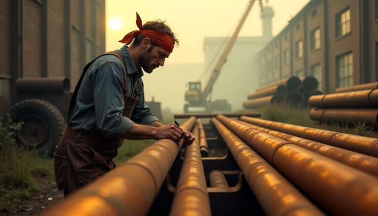
Male construction worker marking steel pipes at an outdoor industrial site during sunset, surrounded by large pipe stacks and construction equipment.

Conclusion

Successfully implementing cost-saving measures in pipe fabrication projects requires a holistic approach that focuses on efficiency and value at every stage. By systematically addressing these areas, you can unlock significant savings and improve the financial performance of your pipe fabrication projects. Begin your initial assessment today and pave the way for more cost-effective and successful outcomes.

Do you need expert assistance, or are you looking for a fabrication partner that prioritizes cost optimization? Discover SRJ Piping India’s solutions next.

Want to Cut Pipe Fabrication Costs Without Compromising Quality?

Let our experts help you choose the right materials, optimize your design, and streamline your fabrication workflow for significant savings.

Piping Design Secrets – How Top Engineers Maximize Efficiency in Limited Spaces

Piping Design Secrets - How Top Engineers Maximize Efficiency in Limited Spaces

Table of Contents

In today’s rapidly evolving industrial landscape, space is at a premium. Whether it’s a sprawling refinery or a compact pharmaceutical plant, the efficient utilization of available space is paramount for operational efficiency, cost-effectiveness, and safety. Nowhere is this more critical than in piping design, where complex networks of pipes, valves, and equipment must be meticulously arranged within often-confined areas. 

This expert guide, brought to you by SRJ Piping India, delves into the intricate world of piping design for limited spaces, revealing the secrets and strategies employed by top engineers to maximize efficiency and minimize spatial footprint. We will explore advanced methodologies, innovative materials, and cutting-edge technologies that are revolutionizing the design and implementation of piping systems. 

By understanding these principles, senior engineers, project directors, and facility owners can make informed decisions, optimize their operations, and ensure long-term success. This guide is designed to provide you with actionable insights, real-world examples, and a strategic blueprint for navigating the challenges of piping design in the modern industrial era.

The Evolving Industrial Landscape

The industrial landscape is undergoing a significant transformation, driven by several key macro-trends that directly impact piping design and overall facility efficiency. These trends include increasing regulatory scrutiny, the rapid adoption of digital technologies, and a growing emphasis on sustainability.

Regulatory Compliance

Environmental regulations are becoming more stringent, requiring industries to minimize emissions, reduce waste, and implement safer operating procedures. This translates to more complex piping systems that incorporate advanced filtration, containment, and monitoring technologies. The challenge lies in integrating these systems into existing facilities without compromising space or efficiency.

Digital Transformation

The adoption of digital technologies, such as Building Information Modeling (BIM), 3D scanning, and advanced simulation software, is revolutionizing the design of piping systems. These tools enable engineers to create highly accurate virtual models, identify potential clashes, optimize layouts, and simulate system performance before construction even begins. The ability to visualize and analyze piping systems in a digital environment is transforming the design process, enabling greater efficiency and reducing costly errors.

Sustainability Demands

Sustainability is no longer a buzzword; it’s a core business imperative. Industries are actively seeking ways to reduce their environmental footprint, conserve resources, and improve energy efficiency. In piping design, this translates to selecting sustainable materials, optimizing system layouts to minimize pressure drops and energy consumption, and implementing water and wastewater treatment systems that reduce water usage and minimize discharge.

Engineer inspecting interconnected metal pipelines at an industrial facility.

Strategic Imperatives for Efficient Piping Design

To thrive in this evolving industrial landscape, senior engineers and project directors must prioritize several key strategic areas in piping design. These imperatives are essential for maximizing efficiency, minimizing costs, and ensuring long-term operational success.

Optimized Layout Planning

The foundation of efficient piping design lies in meticulous planning of the layout. This involves careful consideration of equipment placement, pipe routing, and accessibility for maintenance and inspection. In space-constrained environments, the challenge is to create a layout that minimizes pipe lengths, reduces the number of bends and fittings, and avoids clashes with other equipment or structural elements. 

Advanced 3D modeling software is invaluable in this process, allowing engineers to visualize the entire system, identify potential issues, and optimize the layout before construction begins. Best practices include conducting thorough site surveys, creating detailed 3D models, and involving all stakeholders in the design review process.

Space-Saving Material Selection

The choice of piping materials can significantly impact the overall space requirements of a system. Traditional materials, such as carbon steel, often require thicker walls to withstand pressure and temperature, resulting in larger pipe diameters and increased space consumption. 

Innovative materials, such as high-strength alloys, composite materials, and thin-walled stainless steel, offer higher strength-to-weight ratios, enabling smaller pipe diameters and reduced space requirements. When selecting materials, engineers must consider factors like pressure and temperature ratings, corrosion resistance, cost, and availability.

Modular Design and Pre-Fabrication

Modular design involves breaking down a complex piping system into smaller, self-contained modules that can be fabricated off-site and then assembled on-site. This approach offers several advantages, including reduced on-site construction time, improved quality control, and minimized disruption to existing operations. 

In space-constrained environments, modular design can be particularly beneficial, as it allows for the construction of complex piping systems in a controlled environment where space is less of a constraint. Pre-fabrication of pipe spools and equipment skids further enhances efficiency, reducing on-site welding and installation time.

Design Optimization Methodologies

Rigorous design optimization methodologies are essential for ensuring that piping systems operate efficiently and reliably. This involves using advanced simulation tools to analyze system performance, identify potential bottlenecks, and optimize pipe sizing, pump selection, and control strategies. 

One key aspect of design optimization is minimizing pressure drops, which can significantly impact energy consumption and system capacity. Techniques such as reducing pipe lengths, minimizing the number of bends and fittings, and optimizing pipe diameters can help reduce pressure drops and improve overall system efficiency.

Advanced Methodologies & Innovations

The field of piping design is constantly evolving, with new technologies and methodologies emerging to address the challenges of space-constrained environments. These advanced techniques are empowering engineers to create more efficient, compact, and reliable piping systems.

3D Piping Design Techniques

3D piping design is no longer a luxury; it has become a necessity for complex projects. Modern 3D modeling software allows engineers to create highly detailed virtual models of piping systems, incorporating all components, equipment, and structural elements. This enables engineers to visualize the entire system, identify potential clashes, and optimize the layout before construction begins. 

Advanced features, such as clash detection, interference checking, and pipe routing optimization, can significantly reduce errors and improve overall design efficiency. Furthermore, 3D models can be used to generate accurate fabrication drawings, material takeoffs, and construction documents.

Space-Saving Pipe Fittings

Traditional pipe fittings, such as elbows, tees, and reducers, can consume a significant amount of space in a piping system. Innovative space-saving fittings provide a more compact alternative, enabling engineers to minimize the overall footprint of the system. 

Examples include compact elbows with tighter bend radii, reducing tees with shorter branch lengths, and flangeless fittings that eliminate the need for bulky flanges. These fittings can be handy in congested areas, where space is at a premium.

Computational Fluid Dynamics (CFD) Simulation

CFD simulation is a powerful tool for analyzing fluid flow and heat transfer in piping systems. By creating a virtual model of the system and simulating fluid behavior, engineers can identify areas of high pressure drop, turbulence, or stagnation. 

This information can then be used to optimize the design, improve system performance, and reduce energy consumption. CFD simulation is beneficial for complex piping systems with non-standard geometries or flow conditions.

Risk Mitigation & Resilience Strategies

In industrial piping design, risk mitigation and resilience are paramount. Piping systems are often critical components of plant operations, and failures can lead to costly downtime, environmental damage, and even safety hazards. Therefore, it is essential to implement robust strategies for identifying, assessing, and mitigating risks.

HAZOP Studies

Hazard and Operability (HAZOP) studies are a systematic method for identifying potential hazards and operability problems in a piping system. A multidisciplinary team reviews the design, operating procedures, and possible failure modes to identify potential risks and recommend mitigation measures. HAZOP studies are typically conducted during the design phase and are repeated periodically throughout the system’s life.

Stress Analysis

Stress analysis is a critical component of piping design, particularly for systems operating at high pressures or temperatures. Stress analysis involves calculating the stresses and strains in the piping system due to internal pressure, thermal expansion, external loads, and other factors. This information is used to ensure that the piping system is strong enough to withstand these stresses without failure. Finite element analysis (FEA) software is commonly used for performing stress analysis on complex piping systems.

Corrosion Prevention

Corrosion is a significant threat to the integrity of piping systems, particularly in harsh industrial environments. Implementing effective corrosion prevention strategies is essential for ensuring the long-term reliability of the system. These strategies include selecting corrosion-resistant materials, applying protective coatings, implementing cathodic protection systems, and monitoring corrosion rates. Regular inspection and maintenance are also critical for detecting and addressing corrosion issues before they lead to failures.

Aerial view of a complex network of steel pipes and walkways in an oil refinery.

Future Outlook & Expert Predictions

The future of piping design is promising, with new technologies and methodologies poised to enhance efficiency, safety, and sustainability further. Here are a few expert predictions on where the industry is headed:

Increased Adoption of Digital Twins

Digital twins are virtual replicas of physical assets, such as piping systems, that are continuously updated with real-time data from sensors and other sources. These digital twins can be used for monitoring system performance, predicting failures, and optimizing maintenance schedules. The adoption of digital twins is expected to accelerate in the coming years, enabling engineers to make more informed decisions and improve overall system reliability.

AI-Powered Design Optimization

Artificial intelligence (AI) is poised to revolutionize piping design by automating repetitive tasks, optimizing layouts, and predicting system performance. AI algorithms can analyze vast amounts of data to identify optimal pipe routing, select the most efficient equipment, and minimize energy consumption. As AI technology matures, it is expected to become an indispensable tool for piping designers.

Sustainable Materials and Practices

The focus on sustainability will continue to drive innovation in piping materials and practices. Expect to see increased use of recycled materials, bio-based polymers, and lightweight composites. Additionally, there will be a greater emphasis on reducing water usage, minimizing waste, and implementing energy-efficient designs.

Conclusion

Efficient piping design in limited spaces is a critical challenge for modern industries. By mastering advanced 3D modeling techniques, implementing innovative materials and fittings, utilizing modular design principles, and applying rigorous design optimization methodologies, engineers can overcome these challenges and create piping systems that are efficient, reliable, and sustainable. 

As the industrial landscape continues to evolve, expert-driven planning and innovative solutions will be essential for success. SRJ Piping India is committed to providing cutting-edge piping design solutions that meet the changing needs of our clients.

Schedule a strategic consultation with SRJ Piping India’s experts to discuss your specific piping design challenges and discover how we can help you optimize your operations. Partner with us for your next visionary project and experience the difference that expertise and innovation can make.

Facing Space Constraints in Your Piping Project?

SRJ Piping helps you implement space-saving layouts using 3D design, modular fabrication, and optimized materials.

Top 10 Materials Powering Industrial Piping Projects 

Top 10 Materials Powering Industrial Piping Projects

Table of Contents

In industrial facilities, choosing the right pipeline material is crucial for safety, efficiency, and longevity. A poor choice can lead to costly failures and environmental damage. Factors like extreme temperatures, corrosive chemicals, high pressures, and regulatory demands all influence this complex engineering decision, balancing performance with cost and ease of installation.

This guide outlines the top 10 industrial piping materials, detailing their properties, advantages, disadvantages, typical applications, and key selection considerations. Understanding these materials is crucial for engineers, procurement specialists, and project managers to ensure the robustness and success of industrial piping infrastructure.

Factors Driving Piping Material Decisions

Selecting the ideal pipe material is a multi-faceted process. It’s rarely as simple as picking the cheapest option. Engineers and project stakeholders must consider a wide array of technical, economic, and environmental factors.

Key considerations include:

  • Pressure and Temperature Ratings: Every material has limits. Understanding the maximum operating pressure and temperature of the system is paramount. 
  • Chemical Compatibility: The fluid or gas being transported is a significant factor. Certain chemicals can severely corrode, degrade, or dissolve specific pipe materials.
  • Abrasion Resistance: For systems transporting slurries or solids, the erosive nature of the media must be considered. Some materials withstand abrasive wear well, while others degrade quickly. 
  • Corrosion Resistance: Industrial environments, both internal (process media) and external (atmosphere, soil), can be highly corrosive. Resistance to various forms of corrosion, such as pitting, crevice corrosion, and stress cracking, is vital for long-term integrity.
  • Mechanical Strength and Ductility: The material must withstand physical stresses, including internal pressure, external loads (such as soil or structural weight), and thermal expansion and contraction forces. 
  • Thermal Expansion: Different materials expand and contract at varying rates in response to changes in temperature. This must be accounted for in system design through the use of expansion joints or loops to prevent stress on the piping and connections.
  • Installation and Joining Methods: Welding, flanging, threading, solvent cementing, or mechanical joining methods each have implications for labor, equipment, and inspection requirements. 
  • Cost: Installation costs, maintenance requirements, repair frequency, and potential downtime all contribute to the overall lifecycle cost. 
  • Availability and Sourcing: The ability to reliably source the chosen material in the required quantities and specifications is both practical and crucial. 
  • Regulatory Requirements and Standards: Industrial piping must often comply with strict codes and standards (e.g., ASME, ASTM, API) depending on the industry and application.
A low-angle shot within a deep trench shows two orange pipes laid in the earth, with construction workers and heavy machinery visible above ground under a bright, sunny sky.

The Top 10 Industrial Piping Materials Explored

Now, let’s dive into the materials that form the backbone of industrial piping systems worldwide. Each offers a unique balance of properties suited to specific applications.

Carbon Steel Pipe

Carbon steel is the most widely used material in industrial piping. Its popularity stems from its strength, durability, cost-effectiveness, and ease of fabrication, particularly through welding. It is an alloy of iron and carbon, with carbon content typically ranging from 0.02% to 2.1% by weight. 

Advantages:

  • High tensile strength and durability.
  • Relatively low cost compared to alloys.
  • Excellent weldability and ease of fabrication.
  • Suitable for high-pressure and moderate-to-high-temperature applications.
  • Wide availability in various sizes and schedules (wall thicknesses).

Disadvantages:

  • Prone to rust and corrosion, especially in wet or corrosive environments. Requires external coatings, linings, or cathodic protection.
  • Limited resistance to highly corrosive chemicals.
  • Not suitable for very low temperatures (becomes brittle) or extremely high temperatures, where creep becomes a factor without specific alloying.

Stainless Steel Piping

Stainless steel stands out for its exceptional corrosion resistance, making it indispensable in environments where carbon steel would quickly degrade. It’s an alloy primarily composed of iron, chromium (with a minimum of 10.5%), and often nickel, molybdenum, and other elements. 

Advantages:

  • Excellent corrosion resistance across a wide range of media, including many acids and alkalis.
  • High strength and durability, even at elevated temperatures.
  • Aesthetic appearance (though less relevant in industrial settings).
  • Good resistance to oxidation and scaling at high temperatures.
  • Hygienic and easy to clean, making it suitable for use in the food, beverage, and pharmaceutical industries.

Disadvantages:

  • Higher initial cost compared to carbon steel.
  • Can be susceptible to specific forms of corrosion (e.g., pitting in high-chloride environments, stress corrosion cracking in certain conditions).
  • Welding requires specific techniques to maintain corrosion resistance.

Alloy Steel Pipe

Alloy steels are variations of carbon steel that contain significant amounts of other elements, such as chromium, molybdenum, vanadium, manganese, and silicon. These additions enhance specific properties such as strength, hardness, toughness, wear resistance, and crucially for piping, resistance to high temperatures and corrosion beyond what carbon steel offers.

Advantages:

  • Improved strength and toughness compared to carbon steel.
  • Enhanced high-temperature performance and creep resistance.
  • Better corrosion resistance than carbon steel, though less than stainless steel for general corrosion.
  • It can be heat-treated to achieve a wide range of mechanical properties.

Disadvantages:

  • Higher cost than carbon steel.
  • Weldability can be more challenging than that of carbon steel, often requiring both pre- and post-weld heat treatments.
  • Selection requires careful consideration of the specific alloying elements and their impact on properties.

Copper Piping

Copper piping is a popular choice due to its excellent thermal conductivity, corrosion resistance (especially to water), durability, and ease of joining using soldering or brazing techniques. It has been a staple in plumbing for decades, but also finds significant applications in specific industrial settings.

Advantages:

  • Excellent thermal conductivity, making it ideal for heat exchange applications.
  • Inherently corrosion resistant to potable water and many other fluids.
  • Durable and long-lasting.
  • Easy to cut, bend, and join, making installation simpler.
  • Naturally antimicrobial properties.

Disadvantages:

  • Higher cost than plastics and carbon steel.
  • Susceptible to corrosion from certain chemicals (e.g., ammonia, some acids) and aggressive water chemistry.
  • Not suitable for very high pressures or temperatures compared to metals like steel.
  • Can be a target for theft due to scrap value.

PVC Pipe (Polyvinyl Chloride)

PVC is a thermoplastic polymer widely used for various low-pressure industrial applications. It’s known for being lightweight, inexpensive, and resistant to many chemicals and corrosion.

Advantages:

  • Low cost and easy availability.
  • Excellent resistance to corrosion, rust, and chemical attack from a wide range of acids, alkalis, and salts.
  • Lightweight and easy to handle, it can be installed using solvent cement or mechanical joints.
  • Smooth bore results in low friction loss.
  • Good electrical insulator.

Disadvantages:

  • Limited pressure and temperature capabilities compared to metals. Becomes brittle at low temperatures and loses strength at higher temperatures (typically limited to around 140°F or 60 °C).
  • Can degrade when exposed to UV radiation (requires UV inhibitors or painting for outdoor use).
  • Not suitable for flammable materials due to low melting point.
  • Mechanical strength is significantly lower than that of metallic pipes.

CPVC Pipe (Chlorinated Polyvinyl Chloride)

CPVC is a thermoplastic produced by the chlorination of polyvinyl chloride (PVC) resin. This chemical modification significantly enhances CPVC’s temperature and pressure handling capabilities compared to standard PVC, while retaining many of PVC’s desirable properties, such as corrosion resistance.

Advantages:

  • Good resistance to corrosion and a wide range of chemicals, similar to PVC.
  • Higher temperature rating than PVC (typically up to 200°F or 93 °C).
  • Higher pressure rating than PVC at elevated temperatures.
  • Lightweight and easy to install using solvent cement.
  • Low thermal conductivity compared to metals.

Disadvantages:

  • Higher cost than PVC.
  • Still limited pressure and temperature range compared to metals.
  • It can be affected by certain solvents.
  • Mechanical strength is lower than that of metallic pipes.

HDPE Pipe (High-Density Polyethylene)

HDPE is a flexible thermoplastic pipe known for its toughness, corrosion resistance, and excellent resistance to abrasion and fatigue. It is often joined using heat fusion, creating strong, leak-free joints.

Advantages:

  • Excellent resistance to corrosion, chemicals, and UV radiation.
  • Highly resistant to abrasion, making it suitable for abrasive slurries.
  • Flexible, allowing it to withstand ground movement (earthquakes, soil settlement) and be installed in challenging terrains.
  • Low friction factor provides excellent flow characteristics.
  • Lightweight and easy to handle and install.
  • Heat fusion joining creates strong, leak-proof, monolithic systems.
  • Good fatigue resistance.

Disadvantages:

  • Lower pressure and temperature ratings than metallic pipes.
  • Can deform or creep under sustained high pressure or temperature.
  • Requires specialized heat fusion equipment for joining.
  • Relatively high thermal expansion requires careful design consideration.

FRP/Composite Piping (Fiber Reinforced Polymer)

FRP piping, also known as GRP (Glass Reinforced Polymer) or composite piping, is made from a polymer resin matrix (like epoxy, polyester, or vinyl ester) reinforced with fibers (typically glass, but also carbon or aramid). These materials can be engineered to provide exceptional corrosion resistance and high strength-to-weight ratios.

Advantages:

  • Outstanding corrosion resistance to a wide range of aggressive chemicals that would attack metals.
  • High strength-to-weight ratio; much lighter than metallic pipes.
  • Low thermal and electrical conductivity.
  • Can be custom-engineered for specific chemical resistance and pressure requirements.
  • Long service life in corrosive environments.

Disadvantages:

  • It can be more expensive than standard metallic or plastic pipes.
  • Mechanical properties can be more complex to predict and can be direction-dependent (anisotropic).
  • Installation often requires specialized training and equipment.
  • Susceptible to damage from mechanical impact.
  • Quality control during manufacturing and installation is critical.

Ductile Iron Pipe

Ductile iron is a form of cast iron treated with magnesium to make the graphite nodules spherical rather than flake-like. This structure provides ductile iron with significantly improved ductility, toughness, and impact resistance compared to traditional grey cast iron, while retaining excellent strength and pressure capability.

Advantages:

  • High strength and pressure resistance.
  • Excellent durability and long service life.
  • Can withstand significant external loads and internal pressure surges.
  • Good resistance to corrosion in many soil types (often used underground).
  • Relatively easy to tap for service connections.

Disadvantages:

  • Heavier than plastic pipes, requiring more effort for handling and installation.
  • Can be susceptible to corrosion in highly aggressive soils or from specific chemicals (often requires internal linings and external coatings).
  • Joining methods (typically mechanical joints with gaskets or flanged joints) differ from those used in welded steel.

Specialty Alloy Piping

Beyond standard stainless and alloy steels, a range of specialty alloys is used for extremely demanding industrial piping applications where conventional materials simply cannot cope. These include nickel alloys (such as Inconel, Hastelloy, and Monel), titanium, zirconium, and tantalum. These materials offer unparalleled resistance to extreme temperatures, pressures, and highly corrosive media.

Advantages:

  • Exceptional resistance to highly aggressive chemicals, including strong acids, chlorides, and reducing environments.
  • Superior high-temperature strength and creep resistance.
  • Excellent resistance to specific forms of localized corrosion (pitting, crevice corrosion) and stress corrosion cracking.
  • Long service life in the most severe operating conditions.

Disadvantages:

  • Extremely high initial cost compared to all other common piping materials.
  • Fabrication and welding require specialized expertise and equipment.
  • Lower availability compared to commodity materials.
  • Can be significantly heavier or require thicker walls for similar pressure ratings compared to high-strength steels.
SRJ Blogs

Emerging Trends and Sustainable Choices

The industrial piping landscape is not static. Innovation continues to introduce new materials and enhance existing ones, while a growing emphasis on environmental responsibility is influencing material selection and sourcing practices for pipe materials.

The Push for Sustainable Piping Materials

Sustainability in industrial piping encompasses several key aspects: the energy and resources utilized in manufacturing, the potential for leaching harmful substances, the durability and lifespan (which reduces replacement frequency), and the ability to recycle or reuse materials at the end of their life.

  • Recycled Content: Using materials with recycled content (such as some metals) or those that are highly recyclable (like metals and certain plastics) is becoming increasingly important.
  • Energy Efficiency of Production: The manufacturing process for specific materials is more energy-intensive than that of others.
  • Longevity and Durability: Materials with a longer service life reduce the need for frequent replacement, conserving resources and minimizing waste.
  • Reduced Leaching: In some applications, preventing the pipe material from leaching substances into the transported fluid is critical for both product purity and environmental safety.
  • Innovative Composites: Research continues into developing composite materials with lower environmental footprints, as well as utilizing bio-based resins and recycled fibers.

While the primary drivers in industrial settings remain performance and safety, considerations regarding the environmental impact of piping materials are gaining traction, influencing long-term infrastructure planning and procurement decisions.

Advanced Manufacturing and Material Sourcing

Advances in manufacturing techniques, such as additive manufacturing (3D printing) for complex components and improved coating and lining technologies, are expanding the possibilities for traditional materials. 

Simultaneously, global pipe material sourcing is becoming increasingly complex, necessitating robust supply chain management to ensure material quality, ethical sourcing, and timely delivery. 

Understanding the origin and manufacturing processes of the pipe materials is becoming increasingly important for quality assurance and sustainability goals.

Conclusion

Selecting the correct material for industrial piping is a critical engineering decision with long-term consequences. Diverse materials, including carbon steel, stainless steel, FRP, HDPE, CPVC, and specialty alloys, each have unique advantages and disadvantages regarding strength, corrosion resistance, weight, and temperature capabilities.

The choice hinges on understanding application-specific demands, including operating conditions, environmental factors, regulations, and lifecycle cost. While steel remains a staple, plastics offer cost-effective, corrosion-resistant, and more sustainable options for specific uses. Aggressive environments may require FRP or specialty alloys, despite higher costs.

Ultimately, successful material selection requires deep knowledge of the media, environment, standards, and material properties, complemented by expert advice. This upfront investment ensures a safe, reliable, durable, and cost-effective piping system, which is crucial for overall industrial success.

Need Help Choosing the Right Piping Material?

From carbon steel to specialty alloys, get expert advice to select the most reliable, cost-effective, and compliant material for your industrial project.

Top 10 Innovations Revolutionizing Industrial Pipe Fabrication

Top 10 Innovations Revolutionizing Industrial Pipe Fabrication

Table of Contents

Pipe fabrication is a critical and complex process in industrial construction, forming the essential piping systems for various sectors, including oil and gas, chemicals, and power generation. Traditionally labor-intensive, hazardous, and prone to inconsistencies, it’s now undergoing a rapid transformation. Driven by demands for speed, quality, safety, cost reduction, and sustainability, the industry is adopting new technologies. 

This article will explore the top 10 innovations, from 3D modeling and digital twins to robotic welding and advanced laser cutting, examining how they are revolutionizing efficiency, quality, safety, and workforce development in industrial pipe fabrication.

The Landscape: Drivers of Innovation in Pipe Fabrication

Before diving into the specific technologies, it is crucial to understand why these innovations are happening now. The push for transformation isn’t arbitrary; it is a direct response to persistent industry challenges and evolving global demands.

Pressure for Efficiency and Shorter Timelines

Industrial projects, whether constructing a new plant or revamping an existing one, operate under intense pressure to minimize downtime and accelerate completion. Traditional manual pipe fabrication can be a bottleneck in the production process. 

Demand for Higher Quality and Consistency

Errors in pipe fabrication can lead to costly rework, delays, and, critically, safety hazards. Leaks, cracks, or incorrect fit-ups can compromise the integrity of entire systems. New technologies offer unprecedented levels of precision and repeatability, resulting in higher-quality components and assemblies. 

Enhanced Safety Standards

Working with heavy pipes, performing hot work such as welding, and operating machinery in a fabrication shop or on a construction site inherently involves risks. Innovations such as automation, remote operation, and advanced personal protective equipment are significantly improving safety standards, thereby reducing the risk of injuries and accidents.

Cost Reduction

While the initial investment in new technologies can be significant, the long-term cost savings, achieved through increased efficiency, reduced rework, lower labor costs per unit, and minimized material waste, are substantial. Innovations help optimize material usage and streamline workflows, directly impacting project budgets.

Sustainability and Environmental Impact

The industrial sector faces increasing scrutiny regarding its environmental footprint. Innovations in pipe fabrication contribute to sustainability in several ways:

  • Reduced material waste through precise cutting and optimized design.
  • Improved energy efficiency in fabrication processes (e.g., more efficient welding).
  • Enhanced system integrity leading to fewer leaks and reduced emissions from operational pipelines.
  • Facilitating the use of new, more sustainable materials.

These drivers together create a fertile ground for the adoption of transformative technologies in pipe fabrication. Let’s explore the top 10 specific innovations leading this charge.

A low-angle, long perspective shot of multiple parallel industrial pipes extending into the distance in a brightly lit factory or warehouse, creating a strong sense of depth and linearity.

Top 10 Innovations Transforming Industrial Pipe Fabrication

Here are the leading technologies and techniques reshaping the industrial pipe fabrication landscape:

Advanced 3D Modeling and BIM Integration

The foundation of modern fabrication begins in the digital realm. Advanced 3D modeling software allows for the creation of highly detailed and accurate digital representations of the entire piping system and individual spools. 

How it Works:

Engineers and designers create precise 3D models of pipes, fittings, valves, and support structures. This model contains information like material specifications, dimensions, welding requirements, and even installation sequences. This data-rich model is then used by fabrication software.

Benefits:

  • Enhanced Accuracy: Eliminates many potential errors that arise from interpreting 2D drawings.
  • Improved Clash Detection: Identifies conflicts between piping, structural steel, electrical conduits, and other elements early in the design phase, preventing costly rework on-site.
  • Optimized Spool Design: Allows for the design of fabrication-friendly spools, minimizing on-site connections.
  • Direct Data Transfer: Fabrication shops can directly import 3D model data into their automated machinery, reducing manual data entry errors.
  • Better Visualization: Provides stakeholders with a clear visual understanding of the final product.

Impact:

BIM integration seamlessly connects the design phase with fabrication, installation, and maintenance. This creates a more efficient, less error-prone workflow from concept to completion. It’s fundamental to unlocking the potential of subsequent innovations.

Digital Twin Technology

Building on the foundation of 3D modeling and BIM, the digital twin creates a dynamic virtual replica of the physical piping system or even the entire facility. It’s not just a static model but incorporates real-time data from sensors and operational systems once the facility is built. 

How it Works in Fabrication:

A digital twin of the fabrication process itself can be created. This twin uses data from fabrication equipment, schedules, material tracking, and quality control checks to simulate and optimize the workflow. It can predict potential bottlenecks, track the progress of every spool in real-time, and provide insights into efficiency.

Benefits:

  • Process Optimization: Simulating different scenarios to identify the most efficient fabrication sequences.
  • Real-time Monitoring: Providing up-to-the-minute status of all fabrication activities.
  • Predictive Maintenance: Using data from automated equipment to predict maintenance needs before failures occur.
  • Improved Traceability: Detailed historical data for every fabricated component.
  • Enhanced Collaboration: Provides a single source of truth for all stakeholders involved in the fabrication process.

Impact:

The digital twin pipe fabrication approach moves beyond just creating components to optimizing the entire production process. It enables data-driven decision-making, resulting in substantial improvements in efficiency, predictability, and cost control.

Robotic Welding Pipe

Perhaps one of the most visually striking innovations, robotic welding has evolved from a niche application to become increasingly common in large-scale pipe fabrication shops. 

How it Works:

Robotic arms equipped with welding torches are programmed using data directly from the 3D model or fabrication software. Vision systems and sensors can guide the robot along the weld joint, adjusting parameters in real-time.

Benefits:

  • Increased Speed and Efficiency: Robots can often weld much faster and with less downtime than manual welders.
  • Superior Weld Quality and Consistency: Robots eliminate human fatigue and variability, producing highly consistent, high-quality welds.
  • Improved Safety: Removes the human operator from hazardous conditions involving heat, fumes, and arc flash.
  • Reduced Rework: The consistency of robotic welds results in fewer defects and a lower need for repairs.

Impact:

Robotic welding pipe is a game-changer for high-volume or highly repetitive welding tasks. While skilled human welders are still essential for complex geometries, tie-ins, and field work, robots handle the bulk of standardized spool fabrication, significantly boosting throughput and quality.

Advanced Laser Cutting

Precise preparation of pipe ends before welding is crucial for a strong, reliable joint. Traditional methods involve sawing, plasma cutting, or oxy-fuel cutting, often requiring secondary beveling and grinding. 

How it Works:

High-powered lasers are used to cut precisely and bevel pipe ends in a single operation. CNC (Computer Numerical Control) systems guide the laser head based on design data.

Benefits:

  • High Precision: Laser cutting offers extremely tight tolerances, ensuring perfect fit-up.
  • Clean Cuts and Bevels: Reduces or eliminates the need for secondary grinding and preparation.
  • Increased Speed: Significantly faster than many traditional cutting methods.
  • Minimal Heat Affected Zone (HAZ): Reduces distortion in the pipe material.
  • Handles Various Materials and Shapes: Capable of cutting different pipe materials and creating complex joint geometries.

Impact:

Laser cutting pipe technology streamlines the preparation phase, which is a critical bottleneck in many fabrication shops. Its speed and accuracy contribute directly to faster assembly and higher weld quality downstream.

SRJ (Stress-Reducing Joint) Fabrication Techniques

Stress-Reducing Joints (SRJ), sometimes referred to as “improved” or “advanced” joint designs, are gaining traction, particularly in high-pressure or high-temperature applications where weld integrity under stress is paramount.

How it Works:

SRJ designs alter the geometry of the weld joint (e.g., using specific bevel angles, root gaps, or land thicknesses) and often involve highly controlled welding procedures. The goal is to distribute stress more evenly across the weld area or shift the peak stress away from the fusion line into the parent material. 

Benefits:

  • Increased Fatigue Life: Joints are more resistant to cracking under cyclic loading.
  • Higher Reliability: Reduces the risk of weld failure in demanding conditions.
  • Potential for Downsizing: In some cases, the increased strength allows for using pipes with thinner walls while maintaining integrity (though this is highly dependent on code and application).
  • Reduced Need for Post-Weld Heat Treatment (PWHT): Certain SRJ designs and welding procedures can potentially reduce or eliminate the need for PWHT, saving time and cost.

Impact:

SRJ fabrication tech represents an innovation in metallurgy and welding engineering applied directly to the fabrication process. It’s crucial for industries where pipe system failure has catastrophic consequences, pushing the boundaries of material performance and weld integrity.

Modular and Advanced Pipe Prefabrication

Prefabrication, the process of assembling pipe spools and larger modules in a controlled shop environment before transporting them to the site, is not a new concept. 

How it Works:

Leveraging advanced 3D modeling and logistics planning, larger sections of the plant’s piping system are fabricated in modules within a shop. These modules are designed for easy transport and rapid assembly at the final location. 

Benefits:

  • Reduced On-Site Work: Moves labor and complex tasks from the less controlled, often hazardous construction site to the safer, more efficient fabrication shop.
  • Improved Quality: Fabrication in a controlled environment leads to higher-quality welds and assemblies.
  • Shorter Project Schedules: On-site assembly of modules is significantly faster than the piece-by-piece construction method.
  • Predictable Costs: Shop fabrication offers more predictable costs compared to variable site conditions.

Impact:

Modular and advanced pipe prefabrication techniques fundamentally alter the construction schedule and logistics. They are becoming essential for large, complex projects aiming for rapid deployment and minimal site disruption.

IoT (Internet of Things) and Data Analytics in Fabrication

Connecting physical assets and processes through sensors and data networks is transforming industrial operations. In pipe fabrication, the IoT allows for the collection and analysis of vast amounts of data from machinery, materials, and personnel.

How it Works:

Sensors are placed on welding machines, cutting tables, material handling equipment, and even raw materials (using RFID tags). These sensors collect data on parameters like machine performance, temperature, vibration, material location, and production rates. 

Benefits:

  • Real-time Monitoring: Provides instant visibility into the status and performance of every piece of equipment and every spool being fabricated.
  • Predictive Maintenance: Analyzing machine data to anticipate failures and schedule maintenance proactively.
  • Improved Workflow Optimization: Identifying bottlenecks and inefficiencies in the fabrication process based on real-time data.
  • Automated Inventory Management: Tracking raw materials and completed spools throughout the shop.
  • Enhanced Quality Control: Monitoring welding parameters in real-time to ensure they stay within specifications.

Impact:

IoT pipe fabrication turns the shop floor into a data-rich environment. This enables smarter operations, better resource allocation, and continuous improvement based on actual performance data, leading to significant gains in efficiency and productivity.

Automated Pipe Spool Handling and Fit-up

Moving heavy and often awkwardly shaped pipe sections and spools is physically demanding and carries safety risks. Furthermore, accurately aligning pipe ends for welding (fit-up) requires precision. 

How it Works: 

Automated systems, including conveyors, robotic arms, and specialized positioners, are utilized to move pipe sections, position them for cutting or welding, and accurately align them for a proper fit-up. 

Benefits:

  • Improved Safety: Reduces the need for manual handling of heavy loads.
  • Increased Efficiency: Automates repetitive and time-consuming tasks.
  • Enhanced Accuracy: Ensures precise alignment for welding, resulting in improved weld quality.
  • Reduced Labor Costs: Frees up personnel to focus on skilled tasks, eliminating the need for manual handling.
  • Faster Throughput: Streamlines the material flow through the fabrication shop.

Impact: 

Automated pipe spool handling and fit-up systems significantly improve the speed and safety of material movement within the shop. They are a key component of fully integrated, automated fabrication lines.

Augmented Reality (AR) for Inspection and Training

Augmented Reality overlays digital information onto the real world, viewed through a headset, tablet, or smartphone. While often associated with gaming, AR has powerful applications in industrial settings, including pipe fabrication.

How it Works:

In inspection, an inspector wearing an AR headset or using a tablet can see a fabricated pipe spool. At the same time, the AR system overlays information from the 3D model, inspection checklists, weld requirements, and historical data directly onto their view of the physical pipe. 

Benefits:

  • Improved Inspection Accuracy and Efficiency: Inspectors have instant access to all relevant data, eliminating the need to refer back to drawings or paperwork.
  • Enhanced Training: Provides interactive, hands-on guidance for complex tasks, reducing training time and errors.
  • Reduced Rework: Helps catch potential errors during the fabrication process rather than during final inspection or installation.
  • Better Documentation: AR systems can often record inspection steps and findings.

Impact: 

AR pipe inspection and training tools bridge the gap between the digital design and the physical product and process. They augment human capabilities, making complex tasks easier and less prone to error, while also offering innovative solutions to the skills gap challenge.

Smart Welding Helmets and Personal Protective Equipment (PPE)

While safety has always been paramount, technology is making PPE more intelligent and more protective. Smart welding helmets are a prime example in pipe fabrication.

How it Works: 

Beyond traditional auto-darkening lenses, smart welding helmets can integrate features such as air filtration systems to protect against fumes, communication systems that allow welders to communicate with supervisors or colleagues without lifting their helmets, and even connectivity to track welding parameters or location for safety monitoring. 

Benefits:

  • Enhanced Safety: Provides superior protection against welding hazards like fumes, arc flash, and particulate matter.
  • Improved Communication: Facilitates more transparent communication in noisy environments, enhancing coordination and safety.
  • Increased Comfort and Productivity: Better ventilation and ergonomics can reduce fatigue.
  • Data Collection: Potential for monitoring worker exposure or tracking compliance with safety protocols.

Impact: 

The development of smart welding helmets and other advanced personal protective equipment (PPE) directly addresses the safety challenges inherent in pipe fabrication. They leverage technology to create a safer working environment for skilled tradespeople.

A wide, bright outdoor shot shows a series of large white industrial pipes extending over shimmering blue water towards a distant horizon, with a large processing plant building visible on the right.

Conclusion

Industrial pipe fabrication is undergoing rapid transformation through key innovations, including advanced 3D modeling and BIM, digital twins, robotic welding, advanced laser cutting, SRJ fabrication technology, modular prefabrication, IoT and data analytics, automated handling, AR for inspection and training, and smart welding helmets. 

While demanding investment in technology and workforce development, these advancements offer significant long-term benefits, including reduced project risk, faster timelines, improved asset performance, and better safety and environmental stewardship. 

Embracing this ongoing technological revolution is crucial for companies to remain competitive in the evolving industrial landscape.

Ready to Modernize Your Pipe Fabrication Process?

Discover how innovative fabrication strategies—robotic welding, modular spooling, digital twin tech—can boost quality, reduce costs, and accelerate delivery.

Top 10 Applications Revolutionizing Industries with Prefabricated Piping Systems

Top 10 Applications Revolutionizing Industries with Prefabricated Piping Systems

Table of Contents

Prefabricated piping systems are revolutionizing construction by allowing complex pipe sections (spools, modules, skids) to be built off-site in controlled factory settings. This approach offers significant advantages over traditional on-site methods, including enhanced safety, superior quality control, accelerated project schedules, reduced waste, and cost savings. 

Increasingly a standard in critical industries, prefabrication is transforming the management of large-scale fluid and gas transfer systems across various sectors, including oil and gas, food processing, healthcare, and power generation.

What Exactly Are Prefabricated Piping Systems?

Before diving into applications, let’s clarify what we mean by prefabricated piping systems. At their core, these systems involve the off-site assembly of piping components – pipes, fittings, flanges, valves, instruments, and sometimes even structural supports and insulation – into larger, ready-to-install units.

The process typically begins with detailed engineering and 3D modeling, enabling precise planning and clash detection before fabrication commences. Materials are sourced, cut, beveled, and welded or joined in a workshop environment, where conditions are controlled, and specialized equipment and skilled labor are readily available. 

Once fabricated and inspected, the prefabricated sections are transported to the construction site. On-site work then shifts from extensive piece-by-piece assembly to the efficient lifting and joining of these larger prefabricated units. The move towards modular construction principles, where larger sections of a plant or facility are built off-site, further amplifies the benefits of prefabricated piping.

The Driving Force Behind the Rise of Prefabrication in Piping

The increasing adoption of prefabricated piping isn’t just about convenience; it’s a strategic response to persistent challenges in complex construction projects. Traditional on-site fabrication is susceptible to numerous variables, including weather conditions, labor availability, skill consistency, limited space for material handling, and welding.

Prefabrication mitigates many of these risks. By shifting fabrication to a controlled shop environment, projects gain:

  • Improved Safety: Reducing on-site welding, cutting, and work at height lowers the potential for accidents.
  • Enhanced Quality: Fabrication under optimal conditions, utilizing specialized equipment and consistent processes, results in higher-quality welds and assemblies, thereby minimizing rework.
  • Accelerated Schedules: Offsite fabrication can run concurrently with other site preparation or civil works, significantly compressing the overall project timeline.
  • Cost Predictability: Shop fabrication costs are generally more predictable than variable field labor and site conditions. Reduced rework and faster completion also contribute to cost savings.
  • Reduced Site Congestion: Less material and labor are required on site, improving logistics and access.
  • Better Material Management: Centralized shop fabrication enables optimized bulk purchasing and material handling, resulting in reduced waste.
A low-angle wide shot of multiple industrial pipelines stretching into the distance towards a large refinery complex with smoking stacks, all silhouetted against a vibrant orange and yellow sunset.

The Top 10 Applications Revolutionizing Industries

Prefabricated piping systems are versatile and adaptable, finding critical applications across a broad spectrum of industries. Here, we explore ten key sectors where their impact is most profound:

Industrial Prefab Piping

General industrial facilities, spanning sectors from manufacturing and assembly plants to mining and pulp and paper, rely heavily on extensive and often complex piping networks to transport raw materials, process fluids, utilities (such as steam, air, and water), and finished products. 

In these environments, pipes can range widely in size, material, and pressure rating, handling everything from abrasive slurries to high-temperature steam. Prefabrication enables the precise fabrication of diverse pipe spools and modules in parallel with other construction activities. 

Applications include process lines, utility lines, fire protection systems, and material handling systems. The ability to fabricate large sections off-site and install them quickly helps bring new manufacturing lines online faster or complete plant expansions with minimal disruption to existing operations.

Prefab Piping in Oil and Gas

The oil and gas industry operates under some of the most demanding conditions imaginable, involving high pressures, extreme temperatures, and often remote or hazardous locations. Reliability, safety, and rapid deployment are paramount. 

In upstream operations, such as offshore platforms or remote well sites, space is limited, and logistical challenges are significant. Prefabricating pipe racks, process skids, and utility modules off-site minimizes the amount of work needed in these challenging environments, significantly improving safety and accelerating hook-up time. 

Downstream facilities, such as refineries and petrochemical plants, feature incredibly complex networks of process piping that handle hazardous and corrosive fluids under extreme conditions. The precision and quality control afforded by shop fabrication are critical for ensuring the integrity and safety of these systems.

Prefab Piping in Chemical Plants

Chemical plants involve the processing and handling of a wide array of potentially corrosive, toxic, or flammable substances. The piping systems in these facilities must be built to the highest standards of integrity, using specialized materials and welding procedures to ensure containment and prevent leaks.

Prefab piping chemical plant solutions are vital because they enable the precise fabrication of complex systems using exotic materials, such as stainless steel, nickel alloys, or internally lined pipes, in a controlled environment.   

Specific applications include reaction loops, distillation columns, heat exchanger circuits, and transfer lines. The ability to complete complex welding and assembly off-site, followed by rapid on-site installation, significantly reduces construction risk and project duration, crucial for bringing new production capacity online quickly and safely.

Prefabricated Piping Power Plants

Power generation facilities, whether fueled by fossil fuels, nuclear energy, or renewable sources (such as concentrated solar or geothermal energy), rely on extensive, high-pressure, and high-temperature piping systems to transport steam, water, fuel, and other working fluids. 

Fabricating these critical components in a controlled shop environment allows for the use of automated welding techniques, heat treatment, and extensive non-destructive testing (such as X-ray or ultrasonic testing) to a level that is difficult and time-consuming to achieve consistently in the field.

Large-bore piping, thick-walled pipes, and complex header systems are particularly well-suited for prefabrication. Modules containing turbine bypass systems, boiler feed systems, or cooling water circuits can be fabricated off-site and installed rapidly, accelerating project schedules for new plant construction or significant upgrades. 

Applications range from the main steam and reheat lines to balance-of-plant piping for cooling water, fuel gas, and auxiliary systems. The predictability and quality benefits of prefabricated systems are essential for meeting tight construction deadlines and ensuring the long-term operational reliability of power infrastructure.

Food Grade Prefab Piping

The food and beverage industry demands piping systems that meet exceptionally high standards of hygiene and sanitation. Pipes must be easily cleanable, free of crevices or dead legs where bacteria can harbor, and often made of materials like polished stainless steel to prevent contamination. 

Shop fabrication enables precision welding (often using orbital welding) and meticulous finishing of stainless steel pipes to achieve the smooth, crevice-free internal surfaces necessary for sanitary applications. 

Prefabricated skids containing process units, such as pasteurizers, heat exchangers, or blending systems, can be built and tested off-site before installation, ensuring that all connections and components meet sanitary design principles.

Pharmaceutical (Pharma) Prefab Piping

Similar to the food industry, the pharmaceutical industry requires piping systems of the utmost purity and integrity, particularly for processing active pharmaceutical ingredients (APIs) and sterile water systems (WFI—Water for Injection).

Prefabricated piping for pharmaceutical applications is crucial because it enables the controlled fabrication of high-purity piping using materials such as 316L stainless steel with specific surface finishes (e.g., electropolished).

Prefabricated skids for process units, clean utility generation (including pure steam and WFI), and distribution loops are standard. Building these complex, sensitive systems off-site minimizes the risk of contamination from the construction environment and allows for thorough factory acceptance testing (FAT) before transport.

Prefab Piping in Water Treatment Plants

Water treatment plants (for both potable water and wastewater) utilize complex piping networks to transport raw water, chemicals, treated water, and sludge. These systems often involve large diameter pipes, various materials (including plastics like PVC and fiberglass, steel, and concrete), and operate at relatively low pressures but high volumes.

Prefab piping water treatment solutions offer advantages in fabricating large-bore piping spools, manifold systems, and pipe racks. While pressures are lower than in power or chemical plants, the sheer volume of piping and the need for corrosion-resistant materials make prefabrication a viable option. 

Complex valve arrangements, chemical dosing skids, and filter lateral systems can also be prefabricated as modules. This minimizes on-site work in sometimes wet or challenging environments and allows for better quality control on joints, particularly critical for preventing leaks in water infrastructure.

HVAC Prefab Piping

Heating, Ventilation, and Air Conditioning (HVAC) systems in large commercial buildings, hospitals, data centers, and industrial facilities require extensive piping for chilled water, hot water, steam, and condensate. 

HVAC prefab piping involves fabricating pipe mains, branch lines, and pump or chiller connection spools in a fabrication shop. This enables faster and more precise assembly using automated equipment where possible. 

The benefits of HVAC include reduced labor costs on-site, improved safety by minimizing overhead work and hot work, and accelerated installation schedules. This is particularly valuable in projects with tight deadlines or in renovation projects where minimizing disruption is critical. 

Applications include primary and secondary chilled water loops, heating hot water systems, steam distribution, condensate return, and condenser water systems. The shift to HVAC prefab piping is a key strategy for improving efficiency and coordination between trades in modern building construction.

Prefab Piping in Shipbuilding and Marine

Ships and offshore vessels are floating industrial facilities with incredibly complex and space-constrained piping systems. These include systems for propulsion (fuel, steam, and cooling), ballast water, cargo handling, firefighting, and utilities. Fabrication often takes place in tight, difficult-to-access areas within the hull.

Prefabricated piping systems are standard practice in modern shipbuilding. Entire sections of pipework are fabricated into spools and modules in a dedicated pipe shop, complete with supports, valves, and insulation where possible. These are then transported to the shipyard and installed into pre-erected hull blocks or modules before the blocks are joined together.

This approach significantly reduces the amount of fitting and welding required within the ship’s structure, thereby improving safety, quality, and efficiency dramatically. It also allows piping installation to happen concurrently with the assembly of hull blocks, accelerating the overall construction schedule. 

Applications span virtually every piping system on a vessel, from engine room systems to deck piping and accommodation utilities. Prefabrication is fundamental to the modular construction techniques used in modern shipyards, enabling the rapid and precise assembly of highly complex vessels.

Prefab Piping in Data Centers and High-Tech Facilities

Data centers, semiconductor manufacturing plants, and other high-tech facilities require sophisticated and highly reliable piping systems for cooling (chilled water, condenser water), specialized gases, and critical utilities. Downtime is incredibly costly, making reliability and speed of deployment essential.

Prefabricated piping for data centers and high-tech facilities focuses on systems that require high reliability and often high purity. Chilled water and condenser water loops, which are essential for cooling critical IT equipment, are frequently prefabricated to ensure high-quality welds and connections, thereby minimizing the potential for leaks. 

Prefabricated skids containing pump sets, heat exchangers, and associated piping can be built and tested off-site, significantly reducing the time required for mechanical room setup and installation. In semiconductor facilities, ultra-high-purity (UHP) gas and chemical delivery systems, requiring specialized welding and meticulous cleanliness, benefit immensely from controlled shop fabrication.

The rapid expansion needs of the data center industry, coupled with the demand for extreme reliability and speed to market, make prefabricated piping a critical strategy. It enables faster, more predictable construction while ensuring the high quality necessary for the uninterrupted operation of critical IT and manufacturing infrastructure.

A close-up, shallow depth of field shot of an industrial pipeline with a pressure gauge prominently featured, against a blurred background of a sunset with warm, golden light.

Why Prefabrication is the Future of Piping?

Looking ahead, the trajectory for prefabricated piping systems is one of continued growth and innovation. Several factors point towards prefabrication becoming the default method for complex piping projects:

  • Integration of Advanced Technologies: The increasing use of BIM, digital twinning, and AI-driven planning tools will further optimize the design and fabrication process, minimizing errors and enhancing predictability. 
  • Focus on Sustainability: Shop fabrication can lead to reduced material waste compared to on-site cutting and fitting. 
  • Addressing Labor Shortages: As skilled on-site labor becomes scarcer, shifting complex welding and fitting tasks to a centralized fabrication shop staffed by specialized technicians offers a viable solution.
  • Increased Complexity: As industrial and infrastructural projects become more complex, the logistical and technical challenges of on-site piping fabrication grow exponentially. 
  • Standardization: The growing adoption of modules and connection points is leading to increased standardization, further streamlining the design and installation process.

Conclusion

Prefabricated piping systems are now a fundamental element in modern industrial and construction projects, moving beyond their niche origins. They offer significant benefits across diverse sectors, including oil & gas, chemical, power generation, water treatment, food, and pharmaceutical industries.

These systems improve safety, quality, and project timelines by shifting complex pipe fabrication from hazardous on-site environments to controlled workshops. This includes specialized applications like high-purity piping for pharmaceuticals, high-pressure welding for power plants, and space-optimized designs for shipbuilding.

While requiring thorough upfront planning and coordination, this approach significantly reduces project risks, enhances quality, accelerates completion, and often lowers overall costs, making it a crucial strategy for successful construction, expansion, or upgrade projects. 

Engaging with prefabrication experts early is key to maximizing these benefits.

Planning a Prefabricated Piping Project?

Get expert guidance on modular piping strategies that reduce risks, accelerate timelines, and ensure superior quality in every industry.

Top 10 Welding Techniques Used in Pipe Manufacturing

Top 10 Welding Techniques Used in Pipe Manufacturing

Table of Contents

Pipe manufacturing is fundamental to industries worldwide, supplying essential networks for oil, gas, water, and various industrial processes. The reliability of these piping systems hinges entirely on the strength and quality of their welds; a single faulty weld can lead to catastrophic failures.

Given the diverse demands of pipe manufacturing—including material, diameter, wall thickness, application, speed, and quality—a variety of welding techniques are employed. Selecting the appropriate welding process is crucial for achieving production efficiency, minimizing costs, and ensuring the optimal performance and longevity of the final product.

This article explores the top 10 welding techniques used in pipe manufacturing today. We’ll detail the operation, advantages, disadvantages, typical applications, and key influencing factors of each method.

The Core Players: Foundational Pipe Welding Techniques

These versatile and reliable techniques have been industry mainstays for decades, forming the basis for many specialized pipe welding applications.

A close-up shot of a welder wearing a flame-patterned helmet, actively performing TIG welding on a metal pipe, with bright blue light emanating from the arc.

Shielded Metal Arc Welding (SMAW) - Stick Welding

SMAW, or stick welding, is a fundamental and widely used process that employs a consumable flux-coated electrode. The arc created melts the electrode and base material, while the flux provides shielding gas and slag to protect the weld.

For pipes, SMAW is commonly used in field work, repairs, and for smaller diameter pipes due to its portability and ability to weld in various positions.

Advantages: Highly portable, low equipment cost, excellent for positional welding (especially root passes), tolerant of dirty or rusty surfaces.

Disadvantages: Slower, requires frequent electrode changes, produces significant slag, and is challenging for beginners to achieve high quality, resulting in lower deposition rates.

Gas Metal Arc Welding (GMAW) - MIG Welding

GMAW, or MIG welding, is a semi-automatic or automatic welding process that utilizes a continuously fed wire electrode and an external shielding gas. It’s known for its speed and ease of use.

MIG welding is increasingly popular in shop fabrication, where pipes can be rotated, offering higher deposition rates and faster welding speeds than SMAW. Positional welding can be challenging without skilled operators and specialized techniques.

Advantages: High deposition rates, faster welding speeds, minimal slag, relatively easy for basic welding, and suitable for thicker materials.

Disadvantages: Less portable (requires gas cylinder), sensitive to wind, struggles with out-of-position pipe welding (especially root passes without specific variations), less tolerant of surface contaminants.

Flux-Cored Arc Welding (FCAW)

FCAW is similar to GMAW but uses a tubular electrode wire containing flux for shielding. Some FCAW processes also use external gas (Gas-Shielded FCAW), while others rely solely on the flux (Self-Shielded FCAW).

FCAW is highly productive for thicker materials. Self-shielded FCAW is particularly useful in field applications due to its wind resistance and the absence of a separate gas cylinder. It can also handle positional welding well, making it suitable for fill and cap passes in pipe welding.

Advantages: High deposition rates and speed, good penetration, effective on thicker sections. Self-Shielded is suitable for outdoor conditions and offers better positional welding capabilities than conventional MIG welding.

Disadvantages: Produces slag and generates more fumes than GMAW or GTAW. Self-shielded versions can be less aesthetically pleasing and produce more spatter, making them often unsuitable for critical root passes.

Gas Tungsten Arc Welding (GTAW) - TIG Welding

GTAW, or TIG welding, uses a non-consumable tungsten electrode and an inert shielding gas (usually pure argon). Filler metal is added separately.

TIG welding is synonymous with high-quality, precise pipe welds. It offers exceptional control over heat input and the weld puddle, making it ideal for root passes on open butt pipe joints, especially for stainless steel, aluminum, and other alloys where integrity and appearance are crucial. It produces minimal spatter and no slag, essential for process piping.

Advantages: Immaculate, high-quality welds; excellent control; ideal for root passes and critical applications; effective on thin-wall pipes and exotic materials; visually appealing welds.

Disadvantages: Slower, low deposition rate, high operator skill required, less economical for thick sections, sensitive to contaminants.

Submerged Arc Welding (SAW)

SAW is an automated or semi-automated process where the arc and molten weld pool are submerged under granular flux. The flux provides shielding and contributes alloying elements.

SAW is a highly efficient method, especially for manufacturing large diameter, thick-walled pipes (like pipelines). It offers exceptionally high deposition rates and deep penetration. SAW is typically performed in the flat position, requiring the pipe to be rotated or a moving welding head to be used. 

Advantages: Very high deposition rates and welding speeds (especially multi-wire setups), deep penetration, consistent, high-quality welds, minimal spatter and fumes, suitable for thick materials.

Disadvantages: Limited to flat or horizontally rotated positions, requires significant flux recovery, requires automation equipment, and is not suitable for thin materials or positional welding.

Electric Resistance Welding & High-Frequency Induction Welding

ERW and its advanced variant, HFIW, use heat generated by electrical resistance to join material, distinct from arc welding. They are primarily used for producing straight seams in pipes at extremely high speeds.

In pipe manufacturing, these methods bring the edges of formed steel strip together, applying pressure while passing current through them (ERW) or using induction coils to heat the edges (HFIW). The heat melts the edges, and pressure forges them without the use of filler metal. HFIW, utilizing higher frequencies, provides faster speeds and enhanced control over the heat-affected zone.

Advantages: Extremely high production speeds, highly automated, produces uniform welds, requires no filler metal, offers a clean process, and is suitable for continuous long lengths of pipe.

Disadvantages: Limited primarily to straight seams, requires specialized high-speed manufacturing equipment, is less flexible for various pipe sizes, and traditionally has had issues with weld line consistency.

Plasma Arc Welding (PAW)

PAW utilizes a constricted arc that passes through a copper nozzle, producing a highly concentrated, high-temperature plasma arc. This focused energy enables faster welding speeds, deeper penetration, and narrower welds compared to TIG.

PAW for pipes is used in applications requiring high speed and precision, often on stainless steel or other alloys. It can perform keyhole welding (melting completely through the joint), effective for single-pass welds on specific wall thicknesses. Like TIG, it demands careful control and setup.

Advantages: High energy concentration, faster speeds than TIG, deeper penetration, narrow welds, suitable for keyhole welding, and produces high-quality welds.

Disadvantages: More complex equipment than TIG, requires precise joint fit-up, is challenging in out-of-position welding, and has a higher equipment cost.

Laser Beam Welding (LBW)

Laser beam welding utilizes a highly concentrated beam of coherent light as the heat source. It’s known for its extremely high power density, fast welding speeds, narrow welds, and minimal heat-affected zone.

Laser welding pipe is a relatively new technology in large-scale pipe manufacturing, gaining traction for the high-precision or high-speed production of smaller diameter or thinner-walled pipes, often made from stainless steel or high-strength alloys. It’s highly amenable to automation.

Advantages: Very high welding speeds, narrow and deep welds, minimal heat-affected zone (HAZ), low distortion, often no filler metal required, highly automatable, and a clean process.

Disadvantages: High equipment cost, requires a very precise joint fit-up, limited gap tolerance, requires strict safety precautions, and is less effective on highly reflective materials without specific setups.

Orbital Welding

Orbital welding pipe is an automated process in which the welding arc (typically TIG, but also MIG or PAW) rotates mechanically around a static pipe joint. Explicitly developed for pipes and tubes, it ensures uniform, repeatable welds, especially in critical applications.

An orbital welding system comprises a power supply, a control system, and a welding head that clamps onto the pipe and travels around its circumference. Parameters are precisely programmed, significantly reducing reliance on manual skill.

Advantages: Produces highly consistent, repeatable, high-quality welds; ideal for critical applications requiring validation; reduces operator influence and fatigue; efficient for numerous similar joints; excellent for root passes and full penetration welds.

Disadvantages: High initial equipment cost, requires programming and skilled technicians for setup, less flexible for highly variable joint configurations or sizes, limited to specific pipe dimensions per head.

Mechanized Welding Systems

Beyond orbital welding, the broader category of mechanized welding systems is crucial in pipe manufacturing. These involve equipment that automates or assists the welder, moving the torch or the pipe along a programmed path or at a controlled speed.

Mechanized systems range from simple pipe rotators with a fixed torch to complex robotic arms. They are used for both longitudinal seams (such as in SAW or GMAW pipe mills) and girth welds, where orbital welding may not be ideal due to size or joint configuration.

Advantages: Increases welding speed and deposition rates, improves weld consistency, reduces welder fatigue, allows easier use of high-efficiency processes.

Disadvantages: Requires setup time and programming, is less flexible than purely manual welding for unique joints, and requires an initial equipment investment.

An overhead shot shows a welder in protective gear, including a helmet and gloves, engaged in a welding operation on large metal pipes, with a bright blue arc and sparks illuminating the work area.

Choosing the Right Pipe Welding Technique

Selecting the optimal welding method for a specific pipe manufacturing task is a critical decision. Several factors must be carefully evaluated:

  • Pipe Material: Different materials (carbon steel, stainless steel, alloys, aluminum) favor specific processes.
  • Pipe Dimensions: Small, thin tubing might use TIG or Laser Welding/Orbital Welding; large, thick pipes often benefit from SAW or high-deposition GMAW/FCAW.
  • Application and Service Conditions: High-pressure, high-temperature, corrosive, or critical applications demand high-integrity welds (e.g., TIG root passes, Orbital Welding). Less critical structural piping might allow more economical methods.
  • Position of Welding: Shop environments that allow for pipe rotation enable flat position welding (SAW, GMAW, FCAW). Field welding in fixed positions requires techniques suitable for positional welding (SMAW, TIG, specialized pulsed MIG/FCAW).
  • Required Production Speed and Volume: High volume necessitates fast, often automated processes (ERW/HFIW, SAW, mechanized GMAW/FCAW).
  • Quality Standards and Codes: Industry-specific codes (ASME, API) dictate acceptable processes, procedures, and welder qualifications.
  • Cost Considerations: Equipment, consumables, labor, and production speed all influence overall economic viability.
  • Site Conditions: Field welding is affected by wind, temperature, and accessibility (e.g., Self-Shielded FCAW for wind tolerance, SMAW for portability).
  • Expert knowledge and sometimes test welds are often required to determine the best fit, usually involving a combination of techniques for different passes (root, fill, cap).

Pipe Welding Quality Control Measures

Robust quality control is paramount for safety and reliability in pipe manufacturing.

Key measures include:

Welding Procedure Specifications (WPS): Detailed instructions for repeatable results.
Procedure Qualification Records (PQR): Proof that a WPS meets required tests.
Welder Performance Qualification (WPQ): Certification of welders’ ability to produce welds according to WPSs.
Material Control: Verification of base material and consumable certifications.
Joint Preparation Inspection: Checking bevel angles, root opening, and land before welding.
In-Process Monitoring: Observing parameters, techniques, and cleaning during welding.
Visual Inspection (VT): First line of inspection for surface defects.
Non-Destructive Testing (NDT): Methods like RT, UT, MT, or PT to detect internal or surface defects.
Destructive Testing (DT): Used for procedure qualification or sampling (tensile, bend, impact tests).
Documentation: Maintaining records of WPSs, PQRs, WPQs, material certifications, and inspection results.

Navigating the complexities of industrial piping systems is a significant responsibility; however, by adopting a structured and proactive approach, you can significantly improve their reliability and safety. Begin your initial assessment today and take the first step toward a more reliable and secure facility.

Do you need expert assistance with a specific challenge, require specialized components, or want to explore comprehensive SRJ piping solutions tailored to your facility’s particular needs? Discover how partnering with experienced professionals can provide the support and expertise you need to overcome your toughest piping challenges next.

Advancements in Pipe Welding Technology

The field of pipe welding is continuously evolving to improve speed, quality, consistency, and safety.

  • Advanced Power Supplies: Offer sophisticated arc control (pulsed welding, waveform control) for better positional welding and simplified setup.
  • Automated and Robotic Welding: Robots are increasingly used for repetitive pipe spool fabrication, particularly with GMAW and FCAW, to achieve high speed and consistency.
  • Digital Connectivity and Data Logging: Modern systems can log welding parameters for quality control, traceability, and optimization.
  • Adaptive Welding Systems: Systems that sense changes and automatically adjust parameters in real-time.
  • Improved Consumables: Development of flux-cored wires and stick electrodes with better positional characteristics, higher deposition rates, and enhanced mechanical properties.
  • Narrow Gap Welding: Techniques that reduce weld metal volume for thick joints, saving time and consumables.
  • Friction Stir Welding (FSW): A solid-state process (no melting) used for materials like aluminum, relevant for specific tube applications.

These technologies are pushing the boundaries of pipe manufacturing, enabling faster production, higher quality, and the use of advanced materials.

Pipe Welding Certification Matters

In critical industries, pipe welding certification for both welding procedures (WPS) and individual welders (WPQ) is often mandatory.

Certification ensures welding adheres to established standards and codes (e.g., ASME Section IX, API 1104, AWS D1.1). Qualified procedures demonstrate that specific welding variables yield necessary mechanical properties and integrity. Certified welders prove their ability to apply these procedures successfully.

Investing in proper training and certification is crucial for fabricators and individuals, as it directly impacts the acceptance and reliability of the final product.

Conclusion

Welding is crucial for pipe manufacturing, transforming raw materials into essential infrastructure. The diverse range of techniques, from foundational SMAW and high-speed GMAW/FCAW to precise TIG and high-volume SAW/ERW/HFIW, alongside specialized Orbital and mechanized systems, boosts quality and productivity in critical applications. 

Selecting the optimal technique requires balancing various factors, including pipe material, size, application, position, speed, and quality standards, often by combining methods for different weld parts. Beyond technique, reliable welds demand meticulous quality control and defect prevention. Continuous technological advancements further enhance production. 

Understanding these techniques is crucial for making informed decisions, ensuring the integrity and longevity of piping systems.

Need Help Choosing the Right Pipe Welding Technique?

Get expert assistance in selecting the ideal welding process for your pipe manufacturing needs—optimize strength, quality, and compliance.

Mastering Industrial Piping Challenges: Your Ultimate How-To Guide

Mastering Industrial Piping Challenges: Your Ultimate How-To Guide

Table of Contents

This guide empowers those responsible for industrial piping systems to tackle common challenges confidently. It offers a clear roadmap for identifying potential issues, such as leaks, corrosion, and pressure problems, before they escalate, providing practical strategies for prevention, maintenance, and repair. 

By understanding root causes and implementing practical solutions, facility managers and engineers can ensure the long-term reliability, safety, and optimal performance of their critical piping infrastructure, avoiding costly downtime and environmental hazards.

Guide to Addressing Industrial Piping Challenges

Addressing challenges in industrial piping isn’t a one-size-fits-all approach. It requires a systematic process that starts with understanding your system and potential failure points, moves through strategic planning and execution, and is sustained by diligent maintenance. Let’s break it down into actionable steps.

A close-up shot of weathered industrial machinery, featuring a large, rusty valve handwheel on a pipe in the foreground, with blue structural elements and a green electrical box in the background.

Conduct a System Assessment and Identify Key Challenges

Before you can fix a problem, you need to know precisely what you’re dealing with. This initial assessment phase is arguably the most critical. It’s like a doctor’s check-up for your piping network.

What to Do:

  • Visual Inspection: Walk the entire piping system, paying close attention to connections, supports, insulation, and low points. Look for obvious signs, such as rust, leaks, sagging pipes, or damaged insulation. 
  • Review Historical Data: Analyze maintenance logs, past incident reports (pipe installation failures, industrial pipe failure reasons), inspection results, and operational data (pressure, temperature, flow rates). 
  • Interview Operators and Maintenance Staff: Those who interact with the system daily often have invaluable insights into unusual noises, vibrations, smells, or operational anomalies that might indicate underlying problems.
  • Identify Common Industrial Piping Challenges Present: Based on your inspection and data review, categorize the types of challenges you’re seeing. 

Why it Matters:

This step provides the foundational knowledge about your system’s current health and specific vulnerabilities. Skipping this or doing it superficially can lead to misdiagnoses, wasted resources on addressing symptoms rather than root causes, and ultimately, continued or even more severe pipe failure.

Pinpoint the Root Causes of Identified Problems

Knowing what is wrong isn’t enough; you need to understand why it is bad. A leak might be the symptom, but the cause could be corrosion, excessive vibration, improper support, or a faulty seal. Root cause analysis prevents recurring issues.

What to Do:

  • Investigate Specific Failure Points: For each significant challenge identified (e.g., a persistent leak in a particular area, signs of considerable pipe corrosion), dig deeper to understand the root cause.
  • Consider Potential Factors: Think about the environment, the media being transported, operational parameters, material properties, and the quality of installation.
  • Analyze Material Compatibility: Ensure the current piping material is suitable for the transported medium and operating conditions. Incorrect material selection is a major contributor to industrial pipe failure.
  • Evaluate System Design and Stress: Look for signs of piping stress caused by thermal expansion, vibration, inadequate support, or external loads. Are expansion joints necessary, but missing?

Why it Matters:

Identifying the actual root cause is the only way to implement a lasting solution. Fixing a leak repeatedly without addressing the underlying corrosion or stress issues is a waste of time and resources, leaving the system vulnerable to larger pipe failure events.

Develop and Plan Targeted Solutions

Once you know the problems and their root causes, it’s time to plan the fixes. This involves selecting the appropriate corrective actions, which may include repairs, replacements, modifications, or adjustments to maintenance procedures.

What to Do:

  • Select Appropriate Repair or Mitigation Strategies: Based on the root cause, choose the best approach. For corrosion, this might involve material upgrades, protective coatings, or chemical inhibition. 
  • Consider Material Selection Carefully: If replacement or new installation is needed, ensure the pipe material selection is correct for the long term. 
  • Evaluate Different Technologies: Research modern solutions like composite wraps for temporary or permanent repairs, advanced protective coatings (protective coating), improved sealing technologies (pipe seals), or specialized monitoring equipment.
  • Plan the Execution: Outline the steps required to implement the solution. This includes isolating the section, draining, implementing safety procedures (lockout/tagout), identifying necessary tools and equipment, personnel, and the expected duration.
  • Include Quality Assurance (QA) and Quality Control (QC) Steps: How will you verify the repair or installation is successful and meets standards?
  • Estimate Costs and Resources: Determine the budget, required labor, materials, and any specialized contractors that may be needed.

Why it Matters:

Effective planning ensures that the chosen solution addresses the root cause, is executed safely and correctly, minimizes downtime, and aligns with budgetary and operational constraints. Poor planning is a common reason for industrial pipe failures, often leading to rushed and ineffective repairs.

Execute Repairs, Replacements, or Modifications with Precision

This is where the rubber meets the road. The best plan in the world means nothing without skilled execution. Precision and adherence to safety protocols are paramount during this phase.

What to Do:

  • Implement Isolation and Safety Protocols: Strictly follow lockout/tagout procedures to ensure safety. Ensure the system is depressurized, drained, purged (if necessary), and free of hazardous materials before beginning work.
  • Execute Repairs/Replacements According to Plan: Whether it’s welding, bolting flanges, applying coatings, or installing supports, ensure all work is done by qualified personnel following industry best practices and the specific procedures outlined in your plan. 
  • Address Installation Defects Proactively: If the project involves new pipe installation or replacing sections, ensure proper alignment, correct torquing of bolts, adequate support placement, and proper joining techniques (welding, threading, bonding).
  • Perform In-Progress Quality Checks: Don’t wait until the end to check the work. Verify weld quality as they are completed, ensure flange faces are clean before sealing (pipe seals), and check coating thickness during application.
  • Manage Changes: If unforeseen issues arise during execution, pause, reassess, and modify the plan as needed. Avoid taking shortcuts that compromise safety or quality.
  • Cleanup and Restoration: After the work is complete, ensure the area is cleaned, tools are accounted for, and any removed insulation or protective coverings are adequately replaced.

Why it Matters:

Flawed execution can negate the benefits of careful planning, introduce new installation defects, or even trigger immediate pipe failure. Adhering to strict procedures minimizes risks and ensures the longevity of the repair or modification.

Test and Verify the Solution

Once the work is complete, rigorous testing is essential to confirm that the problem is resolved and the system is ready to return to service safely. Trust, but verify.

What to Do:

  • Perform Pressure Testing: Hydrostatic or pneumatic testing is a standard method to check for leaks and verify the integrity of welds and joints under pressure (pipe pressure problems). Always follow safety guidelines strictly during pressure testing.
  • Visual Inspection Post-Test: After pressure testing, conduct another thorough visual inspection to look for any signs of leaks, stress, or deformation.
  • Functional Testing: If applicable, test any mechanical components involved, like valves or expansion joints, to ensure they operate correctly.
  • Confirm Pipe Seals Integrity: Specifically check all flange joints and seals for any weeping or signs of failure during and after pressure testing.
  • Document Testing Results: Keep detailed records of test pressures, duration, temperature, and results (pass/fail). This documentation is crucial for compliance and future reference.
  • Address Any Issues Found During Testing: If testing reveals problems, go back to the planning stage to address the new findings before commissioning the system.

Why it Matters:

Testing provides objective proof that your repair or modification was successful, and the system can operate safely under design conditions. Skipping or rushing testing dramatically increases the risk of immediate post-commissioning failure or discovering issues at a critical operational moment.

Implement Ongoing Monitoring and Preventive Maintenance

Repairing a problem is good, but preventing the next one is even better. A robust preventative maintenance program is the backbone of reliable industrial piping systems. This is where pipe maintenance truly shines.

What to Do:

  • Establish a Regular Inspection Schedule: Based on the system’s age, materials, operating conditions, and criticality, set a schedule for routine visual inspections (for signs of piping system failure), non-destructive testing (NDT), and functional checks.
  • Monitor Key Operational Parameters: Continuously track and analyze key operational parameters, including pressure, temperature, flow rates, and vibration levels. 
  • Implement Corrosion Monitoring: For systems susceptible to corrosion, consider techniques like corrosion coupons, probes, or online monitoring systems to track corrosion rates over time. 
  • Plan for Cleaning and Flushing: Schedule periodic cleaning (e.g., pigging, chemical cleaning) to remove buildup that can cause blockages, increase pressure drop, and contribute to corrosion or erosion. 
  • Lubricate and Maintain Mechanical Components: Ensure valves, expansion joints, and supports are properly lubricated and functioning as intended.
  • Utilize Predictive Maintenance Techniques: Investigate technologies such as acoustic monitoring (for detecting leaks), thermal imaging, or vibration analysis to anticipate potential failures before they occur.
  • Maintain Detailed Records: Keep accurate records of all inspections, monitoring data, maintenance activities (pipe maintenance), and repairs. 

Why it Matters:

Proactive maintenance identifies minor problems before they escalate into significant, costly failures. It extends the lifespan of your assets, improves safety, reduces unexpected downtime, and optimizes operational efficiency. It’s a shift from reactive “fix-it-when-it-breaks” to a strategic, cost-saving approach focused on industrial pipe leak prevention and overall system health.

Continuously Improve and Adapt

The industrial environment is dynamic. Processes change, technologies evolve, and you learn from experience. The final step involves utilizing that knowledge to continually improve your piping system management.

What to Do:

  • Review Performance Data: Periodically analyze the data collected in Step 6. Are certain areas failing more frequently? Are your maintenance intervals effective? Are there emerging corrosion indicators?
  • Learn from Failures (Even Small Ones): Conduct a mini-root cause analysis for any failure or near-miss, no matter how minor. What can be learned to prevent it from happening again elsewhere in the system? 
  • Stay Updated on Technologies and Best Practices: Keep abreast of new materials, joining methods, coatings, monitoring technologies, and maintenance techniques. 
  • Refine Maintenance Procedures: Based on performance data and new knowledge, adjust your inspection checklists, maintenance schedules, and repair procedures to optimize efficiency. 
  • Invest in Training: Ensure your maintenance staff and operators are trained on the latest inspection techniques, safety protocols, and troubleshooting methods.
  • Consider Sustainability: Look for opportunities to implement more environmentally friendly practices, such as using durable materials with longer lifespans, optimizing energy efficiency through proper insulation and flow, and managing waste from repairs responsibly. 

Why it Matters:

Continuous improvement ensures your piping management strategy remains effective as conditions change. It helps you leverage new technologies for better performance and safety, reduces long-term costs, and adapts to evolving regulatory and environmental requirements. It’s the difference between managing crises and proactively building resilience.

A detailed, eye-level shot of a complex array of shiny metal industrial pipes, valves, and gauges, indicating a sophisticated fluid or gas processing system.

Conclusion

Navigating the complexities of industrial piping systems is a significant responsibility; however, by adopting a structured and proactive approach, you can significantly improve their reliability and safety. Begin your initial assessment today and take the first step toward a more reliable and secure facility.

Do you need expert assistance with a specific challenge, require specialized components, or want to explore comprehensive SRJ piping solutions tailored to your facility’s particular needs? Discover how partnering with experienced professionals can provide the support and expertise you need to overcome your toughest piping challenges next.

Facing Persistent Piping Problems?

Get expert guidance for diagnosing, fixing, and future-proofing your industrial piping systems—minimize downtime and extend system life.