SRJ Piping India company logo – leaders in fire protection, industrial piping, and heavy structural fabrication solutions

FM200 vs. CO2 Suppression Systems: Which One Should You Choose?

FM200 vs. CO2 Suppression Systems: Which One Should You Choose?

Table of Contents

Protecting critical assets from fire is vital for industrial facilities, data centers, and specialized environments, where water-based systems cause more harm. Gas-based suppression systems like FM200 (clean agent) and CO2 (Carbon Dioxide) are key solutions. Choosing between them is complex, as they differ in operation, advantages, disadvantages, risks, and regulatory needs. 

This guide will compare FM200 and CO2 to help facility managers, engineers, and business owners select the optimal fire suppression system for their specific requirements, ensuring robust protection and peace of mind.

Understanding Fire Suppression Fundamentals

Before discussing the specifics of FM200 and CO2, it’s essential to grasp the basic principles of fire suppression, especially in environments where water is unsuitable. Fire requires three elements to exist: fuel, oxygen, and heat—often referred to as the ‘fire triangle’. Remove any one of these elements, and the fire will be extinguished.

Clean agent fire suppression system with multiple red gas cylinders in a controlled environment.

The Fire Triangle & How Suppression Works

Traditional suppression methods like water primarily work by cooling the heat element of the triangle. However, in environments with sensitive electronics, valuable documents, or certain chemicals, water can cause irreparable damage or even exacerbate the fire (e.g., reacting with certain metals). This is where gaseous suppression systems come into play.

Gaseous Suppression Explained

Gas-based fire suppression systems typically work by either:

  • Oxygen Displacement: Reducing the oxygen concentration in the protected area below the level required to support combustion (usually below 15-16%). CO2 is a primary example of this method.
  • Heat Absorption/Chemical Inhibition involves interfering with the chemical reaction of the fire itself or absorbing heat energy. Clean agents like FM200 work predominantly this way.

Understanding these fundamental mechanisms is key to appreciating the differences in application, effectiveness, and safety between FM200 and CO2 systems.

Deep Dive into FM200 (HFC-227ea)

FM200, chemically known as Heptafluoropropane (HFC-227ea), is one of the most widely recognized and utilized ‘clean agents’. The term ‘clean agent’ refers to electrically non-conductive, volatile, or gaseous fire extinguishants that do not leave a residue upon evaporation. This characteristic makes them ideal for protecting sensitive equipment and valuable assets.

Outdoor red fire hydrant with dual valves and chained caps on a concrete base.

What is FM200 and How Does it work?

FM200 is stored as a liquid under pressure and discharged as a gas. Its primary extinguishing mechanism is the heat absorption from the fire at a molecular level. It interferes with the chemical reaction that sustains combustion. While it does have a minor effect on oxygen concentration, its primary mode of action is thermal absorption and chemical interference.

When discharged, FM200 rapidly reduces the flame’s temperature, breaking the combustion chain reaction almost instantaneously. This rapid action is one of its most significant advantages. The system typically achieves extinguishing concentration in 10 seconds or less.

Key Advantages of FM200

The benefits of FM200 are particularly evident in specific environments:

  • Speed: Extinguishes fires quickly (within 10 seconds), minimizing damage and downtime.
  • Personnel Safety: FM200 is designed for occupied spaces. At design concentrations (typically 7-8%), it is considered safe for human exposure, allowing occupants time to evacuate before or during discharge. It does not significantly reduce oxygen levels to hazardous concentrations.
  • No Residue: Being a clean agent, it leaves no residue, dust, or water behind. This means minimal cleanup is required after discharge, significantly reducing downtime and potential damage to sensitive electronics or materials.
  • Minimal Storage Footprint: Requires relatively less storage space than other agents for the exact protected volume.
  • Effective on Class A, B, and C Fires: Capable of suppressing fires involving ordinary combustibles (A), flammable liquids (B), and electrical equipment (C).

Typical Applications

Given its safety profile and clean nature, FM200 is the preferred choice of clean agent systems for many sensitive and occupied spaces. Common industry use case fire system applications include:

  • Data Centers and Server Rooms (which are used for data centers)
  • Telecommunications Facilities
  • Control Rooms
  • Museums and Archives
  • Medical Facilities
  • Process Control Rooms
  • Electrical Switchgear Rooms
  • Clean Rooms
  • Marine and Offshore Applications (Engine Rooms, Control Rooms)
  • Financial Institutions

Limitations and Considerations

While highly effective and safe for occupants, FM200 does have some drawbacks:

  • Cost: Generally more expensive than CO2 systems for the agent and the initial installation.
  • Environmental Impact: As an HFC (Hydrofluorocarbon), FM200 has a relatively high Global Warming Potential (GWP). While it doesn’t harm the ozone layer, its GWP means its long-term use is subject to international regulations (like the Kyoto Protocol amendments) aimed at phasing down HFCs. 
  • Replenishment Cost: Recharging the system after discharge can be costly due to the agent’s price.

Deep Dive into CO2 Suppression Systems

Carbon Dioxide (CO2) has been used as a fire extinguishing agent for decades. It’s a colorless, odorless, and electrically non-conductive gas naturally present in the atmosphere, although at much lower concentrations than required for fire suppression.

What is CO2 Suppression and How Does it Work?

CO2 fire suppression systems work primarily by reducing the oxygen concentration in the protected area below the level required to sustain combustion. Standard fire extinguishing concentrations for CO2 systems are typically between 34% and 75%, depending on the type of hazard (surface fire vs. deep-seated fire). 

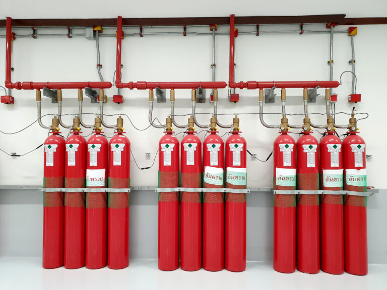
CO2 is stored in high-pressure cylinders as a liquid or in low-pressure refrigerated tanks. When discharged, it rapidly expands into a gas, displacing oxygen. While it does have a minor cooling effect, its main extinguishing power comes from suffocating the fire by oxygen deprivation.

Key Advantages of CO2

CO2 systems offer distinct benefits, particularly in specific industrial settings:

  • Effectiveness on Deep-Seated Fires: CO2 is particularly effective at penetrating and extinguishing deep-seated fires where other agents might only extinguish surface flames. 
  • Cost-Effectiveness: Generally less expensive than clean agent systems like FM200, both in terms of the agent and potentially the initial installation (though system complexity varies).
  • No Residue: Like clean agents, CO2 is a gas and leaves no residue after discharge, eliminating cleanup costs associated with water or foam systems.
  • Electrically Non-Conductive: Safe for use around electrical hazards.
  • Readily Available: Carbon dioxide is a widely available commodity.

Typical Applications

Due to its method of operation and safety hazards, CO2 systems are typically used in areas that are usually unoccupied or where personnel can be reliably evacuated before discharge. Common industry use case fire system applications include:

  • Industrial Processes (e.g., printing presses, dip tanks, spray booths)
  • Flammable Liquid Storage Areas
  • Electrical Substations and Power Generation Facilities
  • Generator Rooms
  • Marine Applications (Engine Rooms, Cargo Holds – often total flooding)
  • Mining Operations
  • Warehouses (specific hazards)
  • Ducts and Extraction Systems (local application)

Significant Limitations and Safety Concerns

The primary and most critical limitation of CO2 suppression systems is their significant danger to human life. This is a key factor when considering CO2 is dangerous to humans:

  • Asphyxiation Risk: At the high concentrations required to extinguish fire (34-75%), CO2 rapidly reduces oxygen levels to life-threatening concentrations (below 15%). 
  • Personnel Hazard: Because of the asphyxiation risk, CO2 systems absolutely must be used in conjunction with robust safety measures, including extensive audible and visual alarms, pre-discharge delays to allow for evacuation, and locked doors or interlocks to prevent accidental entry during discharge. 
  • Cold Hazard: When discharged, liquid CO2 expands rapidly, converting to gas and dry ice particles. This causes a significant temperature drop and, upon direct contact, can cause frostbite or cold burns
Fire pump room with red control panels, green pipes, water pumps, and pressure gauges.

Direct Comparison: FM200 vs. CO2

Now that we’ve examined each system individually, let’s compare them side-by-side to highlight the key differences and help clarify which clean agent system is better for specific scenarios than CO2.

Extinguishing Mechanism: Heat Absorption vs. Oxygen Displacement

This is the most fundamental difference and dictates their suitability and safety profiles. How FM200 and CO2 work is vastly different:

  • FM200: Primarily chemical and physical (heat absorption). It interferes with the fire’s reaction chain and cools the flame. It extinguishes quickly with minimal oxygen reduction.
  • CO2: Primarily physical (oxygen displacement). It reduces the oxygen level below the point of combustion. This is highly effective but creates a lethal atmosphere for humans.

Safety and Personnel Hazard

This is the most critical distinguishing factor and answers the question, is CO2 dangerous to humans emphatically:

  • FM200: Safe for use in normally occupied spaces at design concentrations. Poses minimal risk to human health during discharge, allowing for evacuation time. 
  • CO2: Highly hazardous to human life due to asphyxiation risk at extinguishing concentrations. Must be used in areas that are unoccupied or can be reliably evacuated and secured during discharge. Requires extensive safety protocols and interlocks.

Suitable Applications

Where you need fire suppression is a significant determinant:

  • FM200 is ideal for protecting high-value assets and sensitive equipment in occupied or frequently accessed areas like data centers (which suppresses for data centers), control rooms, museums, archives, and telecommunications hubs.
  • CO2: Best suited for unoccupied spaces or areas with specific hazards where human presence is minimal or strictly controlled, such as industrial process equipment, flammable liquid storage, generator rooms, and electrical substations. Effective on deep-seated fires that FM200 might struggle with.

Cost Comparison

Budget is always a factor, though it shouldn’t be the sole one:

  • FM200: The agent’s initial cost is higher, as are potentially the system components and installation. Replenishment is also more expensive.
  • CO2: Lower initial cost for the agent. System costs can vary depending on complexity (total flooding vs. local application). Generally considered more cost-effective for larger, unoccupied hazards. 

Environmental Impact

Sustainability is an increasing concern:

  • FM200: Has a high Global Warming Potential (GWP), contributing to climate change if released. Subject to phase-down regulations globally. Newer agents with lower GWP are alternatives, but FM200 is still widely used and compliant with current laws in many areas.
  • CO2: While a greenhouse gas, CO2 used in suppression systems is often sourced from industrial processes as a byproduct. Its release during suppression is generally considered a minor contribution compared to industrial emissions. 

Regulatory Compliance

Adhering to standards is non-negotiable:

  • FM200: Governed by standards like NFPA 2001 (Standard on Clean Agent Fire Extinguishing Systems) and relevant national standards (NFPA vs BIS suppression). Compliance focuses on proper design, installation, agent concentration, and system integrity.
  • CO2: Governed by standards like NFPA 12 (Standard on Carbon Dioxide Extinguishing Systems) and national standards. Compliance is stringent regarding safety measures, pre-discharge alarms, delays, signage, and interlocks to mitigate the severe hazard to life. 

System Design & Installation Considerations

The physical setup differs:

  • FM200: Requires a clean agent container, piping network, nozzles, detection system, and control panel. Piping design (suppression system operation) is crucial to ensure rapid and even distribution of the agent.
  • CO2: Also requires containers (often larger or more numerous than FM200 for the same volume due to the higher concentration needed), piping, nozzles, detection, and a control panel. Local application systems have different design requirements than total flooding systems. 

Making the Right Choice: Factors to Consider

Choosing between FM200 and CO2 is rarely straightforward. It involves weighing each system’s technical capabilities against the unique characteristics and requirements of your specific application. As a facility manager, fire insights source, considering all angles is vital.

Risk Assessment & Asset Value

What are you protecting, and what is its value?

  • High-Value, Sensitive Assets (Electronics, Data, Documents): FM200’s clean, non-damaging discharge and minimal downtime make it the preferred choice, especially in places like data centers (which require suppression for data centers). 
  • Assets Tolerant of CO2 Discharge (e.g., industrial machinery, electrical gear): CO2 might be considered, especially if cost is a primary driver and human occupancy is not a factor.

Occupancy & Personnel Safety

Are people present in the protected area, and how often?

  • Occupied Spaces (Offices, Control Rooms, Labs, Data Centers): FM200 or other clean agents are strongly recommended due to their safety profile. 
  • Unoccupied or Restricted Access Areas: CO2 can be a viable option, provided rigorous safety measures are implemented and maintained to prevent personnel exposure.

Type of Fire Hazard

What kind of fires are most likely?

  • Surface Fires (Flammable liquids, electrical fires): Both FM200 and CO2 are effective. FM200 acts faster on Class A and B surface fires by interrupting the reaction.
  • Deep-Seated Fires (Smoldering materials): CO2 is generally more effective at penetrating and extinguishing these fires due to its oxygen displacement mechanism.

Environmental Regulations & Future Proofing

What are the current and future environmental policies?

  • Consider FM200’s GWP and the regulatory landscape regarding HFC phase-downs. While currently compliant, future regulations might favor agents with lower environmental impact (clean agent suppression guide).
  • Ensure compliance with national standards (NFPA vs BIS suppression) and any recent or upcoming CO2 compliance changes in India that might affect system design or safety requirements.

Budget & Long-Term Costs

Look beyond the initial purchase price (fire system cost calculator).

  • Consider installation costs (potentially higher for FM200 piping tolerances, or higher for CO2 due to extensive safety systems).
  • Agent cost and potential recharge costs.
  • The cost of potential business interruption and damage from discharge (potentially lower with FM200).
  • Ongoing maintenance and testing costs (required for both).

Conclusion

FM200 and CO2 are gas-based fire suppression systems for critical assets. FM200 is ideal for occupied spaces and sensitive equipment (like data centers) due to its rapid, clean, and people-safe discharge, despite higher costs and GWP. 

CO2 is effective and cost-efficient for unoccupied industrial areas and deep-seated fires. However, its oxygen displacement method poses a severe risk to human life, requiring strict safety protocols and limiting its use. 

The optimal choice prioritizes life safety, asset protection, compliance (e.g., NFPA, BIS, and any specific CO2 compliance changes in India), and cost-effectiveness, requiring thorough risk assessment and expert consultation.

Consult SRJ Piping India for expert fire suppression system selection, design, and installation tailored to your specific industrial or critical asset protection needs. Our experienced team can help you navigate the complexities of FM200, CO2, and other suppression options to ensure you have the most effective and compliant system.

Choosing between FM200 and CO2 fire suppression systems isn’t just technical – it’s a life-or-death business decision with lasting financial implications. The NFPA 2001 Standard reveals FM200’s 10-second discharge advantage over CO2 in server rooms, while OSHA 1910.162 mandates CO2’s strict safety protocols for industrial use – a dichotomy we navigate daily through our FM Global-Compliant Design Services. When a Bangalore data center’s CO2 system accidentally activated (per this CSB Incident Report), it validated our Pre-Action System Solutions for mission-critical environments. Your choice hinges on three factors: asset sensitivity, occupancy patterns, and total cost of ownership – all decoded in this definitive guide.

FM200 or CO2 – Not Sure What Your Facility Needs?

Our fire safety experts at SRJ Piping India help you choose the right gas suppression system—safe, compliant & cost-effective.

When Sprinklers Fail: 3 Industrial Fire Disasters and Their Root Causes

When Sprinklers Fail: 3 Industrial Fire Disasters and Their Root Causes

Table of Contents

Imagine a bustling manufacturing plant, the heart of local industry, reduced to smoldering ruins. Or a vital distribution warehouse, filled with essential goods, engulfed in flames, disrupting supply chains for months. While fire is a constant threat, modern fire suppression systems, particularly sprinkler systems, are expected to act as the first line of defense. 

Yet, these systems often fail, leading to devastating consequences. 

This article explores three real-world industrial fire disasters in which sprinkler system failures were critical. It delves into the root causes and offers crucial lessons for preventing future catastrophes. It’s a sobering look at how seemingly minor oversights can lead to major disasters and how a proactive approach to fire safety is paramount.

The Client (Or The Scenario)

Let’s consider a composite scenario based on several real-world incidents. “Acme Manufacturing,” a medium-sized industrial plant producing specialized components for the automotive industry, relies heavily on its sprinkler system to protect its valuable machinery and inventory. 

Located in a region prone to harsh winters, Acme faces the challenge of maintaining a fully functional sprinkler system while combating the risk of freezing pipes. The facility manager, pressured by budget constraints, had deferred some maintenance tasks, unknowingly creating vulnerabilities in their fire protection infrastructure.

Low-angle view of an industrial ceiling with exposed ventilation ducts and mounted lights.

The Problem in Detail

The core problem wasn’t a glaring issue but a confluence of factors. An aging sprinkler system, a lack of comprehensive preventative maintenance, and insufficient protection against freezing temperatures created a perfect storm. The system’s design, adequate when initially installed, hadn’t been updated to account for changes in the facility’s layout and the introduction of more flammable materials. 

Furthermore, exposed to the elements, a section of the piping had suffered unnoticed corrosion. All these factors contributed to the sprinkler system’s ultimate failure during a fire, resulting in significant property damage and business interruption.

The SRJ Piping India Solution

At SRJ Piping India, we understand that fire protection is not merely about installing a sprinkler system; it’s about providing a complete, reliable, and well-maintained solution tailored to each client’s needs. In a similar scenario, SRJ Piping India would have implemented a multifaceted approach encompassing risk assessment, system redesign, advanced materials, and ongoing maintenance programs. 

This approach focuses on identifying vulnerabilities and engineering robust solutions that mitigate the risk of sprinkler system failure.

Close-up of an active fire sprinkler system discharging water from a ceiling-mounted safety network.

Implementation Process

The implementation would begin with a thorough facility risk assessment, identifying potential fire hazards and evaluating the existing sprinkler system’s capabilities. A detailed system audit would reveal deficiencies, such as corroded pipes, inadequate water pressure, or outdated components. 

Based on the findings, SRJ Piping India’s engineers would design an optimized sprinkler system, incorporating advanced materials like CPVC for enhanced corrosion resistance and durability. The installation or retrofitting process would be meticulously managed, ensuring compliance with all relevant fire safety codes and regulations.

Finally, a comprehensive preventative maintenance program, including regular inspections, testing, and repairs, would be implemented to ensure the system’s long-term reliability.

Tangible Results and Impact

By addressing the underlying causes of potential sprinkler system failure, SRJ Piping India’s solutions deliver significant and measurable results:

  • Reduced Risk of Failure: Proactive maintenance and advanced materials minimize the likelihood of system malfunction during a fire.
  • Enhanced Fire Suppression Capability: Optimized system design and adequate water pressure ensure effective fire containment and suppression.
  • Minimized Property Damage: Rapid fire suppression limits the spread of flames, reducing damage to equipment, inventory, and the building itself.
  • Business Continuity: The solution helps maintain uninterrupted business operations and minimizes financial losses by preventing major fire incidents.
  • Improved Safety: Protecting employees and visitors from fire dangers is paramount.

In hypothetical quantitative terms, a company implementing such a solution could see:

  • A 50% reduction in the risk of a major fire incident.
  • A 40% decrease in potential property damage costs.
  • A 25% improvement in business continuity metrics.

Incident 1: The Frozen Warehouse

The Scenario: 

A large distribution warehouse in the Midwest experienced a catastrophic fire during a particularly harsh winter. The building, storing various consumer goods, relied on a wet-pipe sprinkler system.

The Failure: 

A section of the sprinkler piping near an exterior wall with inadequate insulation froze and ruptured, resulting in a loss of water pressure throughout the system. The sprinklers failed to activate when a fire broke out in the storage area, allowing the fire to spread rapidly.

The Root Cause:

Inadequate freeze protection measures, combined with deferred maintenance. The warehouse management had neglected to insulate vulnerable pipes properly and failed to inspect the system for signs of damage or freezing regularly.

Lessons Learned: 

This disaster highlights the critical importance of freeze protection in cold climates. While cost-effective, wet-pipe systems are susceptible to freezing. Alternatives like dry-pipe systems (where pipes are filled with pressurized air or nitrogen until a fire is detected) or antifreeze solutions should be considered in vulnerable areas. Regular inspections and maintenance, including checking insulation and pipe integrity, are essential.

Incident 2: The Corroded Factory

The Scenario:

A chemical manufacturing plant suffered a major fire that caused extensive damage. Although the plant had a sprinkler system, it failed to control the fire effectively.

The Failure:

Extensive corrosion within the sprinkler piping had significantly reduced water flow and pressure. In some areas, the pipes were completely blocked with rust and scale. When the fire ignited, the sprinklers discharged a weak stream of water, insufficient to suppress the flames.

The Root Cause: 

Lack of corrosion monitoring and preventative maintenance. The plant management had not implemented a corrosion control program, allowing the piping to deteriorate over time. The type of piping used was also not suitable for the corrosive environment of the chemical plant.

Lessons Learned: 

Corrosion is a silent killer of sprinkler systems. Regular inspections, including internal pipe assessments, are crucial. In corrosive environments, corrosion-resistant materials, such as CPVC or stainless steel, are recommended. Corrosion inhibitors can also be added to the water supply to slow corrosion. Implementing a comprehensive corrosion management program is essential for ensuring the long-term reliability of the sprinkler system.

Incident 3: The Obstructed Hospital

The Scenario:

A hospital experienced a fire in a storage room. While the sprinkler system was activated, it failed to effectively control the fire, leading to smoke damage and the evacuation of patients.

The Failure:

An obstruction in the sprinkler piping, caused by accumulated debris and sediment, restricted water flow to several sprinkler heads. These heads either failed to discharge water or released only a weak spray.

The Root Cause:

Inadequate flushing and maintenance of the sprinkler system. The hospital management had not followed recommended procedures for periodically flushing the system to remove debris. Construction work in the vicinity had also introduced sediment into the pipes.

Lessons Learned:

Obstructions can significantly impair the effectiveness of sprinkler systems. Regular flushing of the system is necessary to remove debris and sediment. Strainers and filters can be installed to prevent large particles from entering the pipes. Extra precautions should be taken during construction or renovation projects to protect the sprinkler system from contamination.

Close-up view of a ceiling-mounted fire sprinkler head spraying water during emergency activation.

Why Does This Matter for Your Business?

These case studies underscore a crucial point: a fire sprinkler system is only as good as its weakest link. A seemingly minor oversight, such as deferred maintenance or inadequate freeze protection, can have catastrophic consequences. 

By understanding the common causes of sprinkler system failure and implementing proactive preventive measures, businesses can significantly reduce their risk of fire damage and ensure the safety of their employees and assets. 

SRJ Piping India specializes in providing comprehensive fire protection solutions that address these vulnerabilities, ensuring your sprinkler system is always ready to perform when needed. 

Don’t wait for a disaster; take proactive steps to protect your business today.

Client Testimonial / Success Quote

“SRJ Piping India delivered beyond our expectations, ensuring our facility operates efficiently and safely. Their expertise in fire protection systems is unparalleled, and their proactive approach has given us peace of mind.”

Conclusion

The stories of the frozen warehouse, the corroded factory, and the obstructed hospital are stark reminders of the critical importance of fire safety and the potential consequences of sprinkler system failure. The root causes of these disasters are often preventable, from inadequate freeze protection to corrosion and obstructions. 

By understanding these risks and implementing proactive measures, businesses can significantly reduce their vulnerability to fire. SRJ Piping India is committed to providing comprehensive fire protection solutions that address these challenges and ensure the safety of your employees, assets, and business operations.

Facing similar challenges? Contact SRJ Piping India today for a custom solution.

When industrial sprinklers fail, the results aren’t just statistics – they’re preventable tragedies etched in scorched steel and lost lives. The NFPA 25 Post-Incident Database reveals 71% of sprinkler failures stem from maintenance neglect – a chilling reality we combat through our FM Global-Compliant Inspection Protocols. This investigation exposes three catastrophic Indian incidents:

  1. A Pune chemical plant where frozen pipes (violating IS 15105:2002) caused ₹87Cr in damages

  2. A Delhi warehouse whose blocked sprinklers ignored NFPA 13’s clearance rules

  3. A Chennai auto parts factory where improper corrosion protection led to system-wide rupture

These aren’t accidents – they’re cascading failures of vigilance that our Pre-Action Sprinkler Solutions are engineered to prevent.

Worried About Sprinkler System Failures?

Don’t wait for disaster. Get your fire protection system inspected and upgraded by SRJ Piping India’s experts.

The Ultimate Guide to Emergency Response Systems for Industrial Facilities in 2025

The Ultimate Guide to Emergency Response Systems for Industrial Facilities in 2025

Table of Contents

Industrial facilities present unique challenges when it comes to emergency response. The complexity of operations, hazardous materials, and the sheer scale of these sites demand robust and well-rehearsed emergency response systems. As we approach 2025, technological advancements, evolving regulatory landscapes, and emerging threats necessitate re-evaluating and upgrading these systems. 

This comprehensive guide will equip you with the knowledge and strategies to develop, implement, and maintain state-of-the-art emergency response systems, ensuring the safety of your personnel, the protection of your assets, and the continuity of your operations. 

Team of engineers and safety officers reviewing emergency protocols at an industrial site.

What is an Emergency Response System (ERS)?

An Emergency Response System (ERS) is a comprehensive framework of policies, procedures, resources, and technologies designed to mitigate the impact of unforeseen events that threaten the safety of personnel, the environment, property, or business operations. It’s a proactive approach encompassing preparedness, response, and recovery efforts.

Key Objectives of an ERS

The primary objectives of an ERS are to:

  • Protect Human Life: This is always the top priority.
  • Minimize Injuries: Implementing strategies to reduce the severity of harm.
  • Protect Property and Assets: Safeguarding physical resources from damage or loss.
  • Protect the Environment: Preventing or minimizing environmental contamination.
  • Ensure Business Continuity: Recover operations as quickly and efficiently as possible.
  • Comply with Regulations: Meeting all legal and regulatory safety and emergency response requirements.

Types of Industrial Emergencies

Industrial facilities face a wide range of potential emergencies, including:

  • Fires and Explosions: Often triggered by flammable materials, equipment malfunctions, or human error.
  • Hazardous Material Releases: Accidental spills or leaks of toxic chemicals or gases.
  • Natural Disasters: Earthquakes, floods, hurricanes, and other weather-related events.
  • Equipment Failures: Malfunctions in critical machinery or infrastructure.
  • Security Breaches: Unauthorized access, sabotage, or acts of terrorism.
  • Medical Emergencies: Injuries or illnesses requiring immediate medical attention.
  • Cybersecurity Incidents: Data breaches or ransomware attacks that disrupt operations or compromise safety systems.

The Importance of Risk Assessment

A comprehensive risk assessment is the cornerstone of any effective ERS. It involves:

  • Identifying Potential Hazards: Recognizing all possible threats within the facility.
  • Evaluating the Likelihood and Impact: Assessing the probability of each hazard occurring and the potential consequences.
  • Prioritizing Risks: Ranking hazards based on their severity and likelihood.
  • Developing Mitigation Strategies: Implementing measures to reduce or eliminate the identified risks.

Key Components/Phases Of ERS

A well-structured ERS comprises several interconnected components or phases, each crucial to ensuring a swift and effective response.

Prevention

Prevention is the proactive phase focused on minimizing the likelihood of emergencies. Key activities include:

  • Regular Equipment Inspections and Maintenance: Ensuring that machinery and infrastructure are in optimal working condition.
  • Hazardous Material Management: Implementing strict protocols for storing, handling, and disposing of hazardous materials.
  • Safety Training: Providing comprehensive training to all personnel on safety procedures and emergency protocols.
  • Security Measures: Implementing physical and cybersecurity measures to prevent unauthorized access and protect critical systems.
  • Compliance Audits: Regularly assessing compliance with safety regulations and industry best practices.

Preparedness

Preparedness focuses on developing the resources and plans to respond effectively to emergencies. This phase involves:

  • Emergency Response Plan (ERP) Development: Creating a detailed plan outlining procedures for various emergency scenarios. The emergency checklist for factories should be integrated into the ERP.
  • Resource Allocation: Ensure adequate emergency equipment supplies, including fire extinguishers, first aid kits, personal protective equipment (PPE), and communication devices—inventory must-have industrial response items.
  • Training and Drills: Conducting regular training sessions and drills to familiarize personnel with emergency procedures and test the effectiveness of the ERP.
  • Communication Systems: Establishing reliable communication systems for alerting personnel, coordinating response efforts, and communicating with external agencies.
  • Emergency Contact Lists: Maintaining up-to-date contact information for key personnel, emergency services, and regulatory agencies.

Response

The response phase involves the immediate actions taken during an emergency to mitigate its impact. Key activities include:

  • Incident Notification: Promptly alerting personnel and relevant authorities about the emergency.
  • Evacuation Procedures: Implementing pre-defined evacuation routes and procedures to ensure the safe removal of personnel from affected areas.
  • Emergency Shutdown Procedures: Safely shutting down equipment and processes to prevent further damage or escalation.
  • First Aid and Medical Assistance: Providing immediate medical care to injured personnel.
  • Fire Suppression: Deploying fire suppression systems and equipment to extinguish fires.
  • Hazardous Material Containment: Containing and controlling releases of hazardous materials.
  • Coordination with External Agencies: Working with fire departments, law enforcement, and other emergency responders.

Recovery

The recovery phase focuses on restoring operations and returning the facility to a safe and productive state. This phase involves:

  • Damage Assessment: Evaluating the extent of damage to equipment, infrastructure, and the environment.
  • Cleanup and Remediation: Removing debris, cleaning up spills, and remediating environmental contamination.
  • Equipment Repair and Replacement: Repairing or replacing damaged equipment and infrastructure.
  • Incident Investigation: Conducting a thorough investigation to determine the root cause of the emergency and prevent future occurrences.
  • Business Continuity Planning: Implementing strategies to resume operations quickly while minimizing disruption.

Advanced Strategies & Best Practices to Enhance ERS

Beyond the foundational components, implementing advanced strategies and adhering to best practices can significantly enhance the effectiveness of your ERS.

Integrating Technology

Leveraging technology is crucial for modernizing emergency response.

  • Real-Time Monitoring Systems: Implementing sensors and monitoring systems to detect potential hazards, such as gas leaks, temperature fluctuations, or equipment malfunctions.
  • Automated Alert Systems: Utilizing automated systems to quickly notify personnel of emergencies via SMS, email, or mobile apps.
  • Geographic Information Systems (GIS): Using GIS to map facility layouts, identify potential hazards, and track the location of personnel and resources during an emergency.
  • Drones and Robotics: Deploying drones and robots to assess damage, monitor hazardous areas, and assist with search and rescue operations.
  • AI-Powered Analytics: Analyzing data from monitoring systems to identify patterns and predict potential emergencies. The factory safety FAQ should include examples of AI use.

Enhancing Communication

Effective communication is vital during an emergency.

  • Redundant Communication Systems: Implementing multiple communication channels, including radio, satellite phones, and internet-based systems, to ensure reliable communication even during disruptions.
  • Emergency Communication Software: Utilizing software platforms that facilitate mass notifications, two-way communication, and real-time collaboration.
  • Clear Communication Protocols: Establishing clear protocols for communicating information during an emergency, including who is responsible for communicating what information to whom.
  • Multilingual Communication: Ensuring communication materials and procedures are available in multiple languages to accommodate a diverse workforce.

Improving Training and Drills

Regular and realistic training is essential for preparing personnel for emergencies.

  • Scenario-Based Training: Conducting training exercises that simulate real-world emergencies, allowing personnel to practice their response skills.
  • Tabletop Exercises: Facilitating discussions and planning sessions to review emergency procedures and identify potential gaps.
  • Full-Scale Drills: Conducting large-scale drills that involve all personnel and external agencies, providing a realistic test of the ERS.
  • Specialized Training: Providing specialized training to personnel with specific roles in the ERS, such as fire brigade members, first responders, and hazardous material technicians.
  • Competency Assessments: Regularly assessing the competency of personnel in emergency response procedures.

Collaboration and Coordination

Effective emergency response requires collaboration and coordination with external agencies.

  • Memoranda of Understanding (MOUs): Establishing MOUs with local fire departments, law enforcement agencies, and other emergency responders to define roles and responsibilities.
  • Joint Training Exercises: Conducting joint training exercises with external agencies to improve coordination and communication.
  • Community Engagement: Engaging with the local community to raise awareness of potential hazards and emergency procedures.
  • Information Sharing: Information about potential hazards and emergency plans with external agencies and the community.

Challenges, Troubleshooting, & Solutions to Maintain ERS

Implementing and maintaining an effective ERS has its challenges. Understanding these challenges and having effective solutions is crucial.

Common Challenges

  • Lack of Management Support: Insufficient commitment from leadership to prioritize and fund emergency preparedness efforts. The management response protocol should outline commitment.
  • Inadequate Resources: Limited funding, personnel, or equipment to implement and maintain the ERS effectively.
  • Poor Communication: Difficulties communicating information during an emergency due to system failures, language barriers, or a lack of clear protocols. The risks of old emergency systems often include poor communication.
  • Insufficient Training: Inadequate training and drills lead to confusion and ineffective response during an emergency.
  • Complacency: A false sense of security leading to a decline in preparedness efforts.
  • Resistance to Change: Reluctance to adopt new technologies or procedures. Upgrading old emergency systems might face resistance.
  • Cybersecurity Threats: Vulnerability to cyberattacks that could disrupt safety systems or compromise sensitive information.

Troubleshooting and Solutions

  • Gaining Management Support: Present a compelling business case highlighting the benefits of emergency preparedness, including reduced risk of accidents, improved regulatory compliance, and enhanced business continuity. Conduct a factory emergency interview with management to demonstrate value.
  • Securing Adequate Resources: Develop a detailed budget for emergency preparedness efforts and seek funding from multiple sources, including internal budgets, grants, and insurance reimbursements.
  • Improving Communication: Implement redundant communication systems, establish clear communication protocols, and provide multilingual communication materials.
  • Enhancing Training: Conduct regular scenario-based training exercises, provide specialized training to key personnel, and assess competency in emergency response procedures.
  • Combating Complacency: Regularly review and update the ERS, conduct surprise drills, and promote a safety culture.
  • Overcoming Resistance to Change: Communicate the benefits of new technologies and procedures, involve personnel in the implementation process, and provide adequate training.
  • Addressing Cybersecurity Threats: Implement robust cybersecurity measures to protect safety systems and sensitive information, conduct regular security audits, and provide cybersecurity awareness training to personnel.

Future Trends & Innovations of ERS

The field of emergency response is constantly evolving. Staying abreast of future trends and innovations is essential for maintaining a cutting-edge ERS.

Artificial Intelligence (AI) and Machine Learning (ML)

  • Predictive Analytics: Using AI and ML to analyze data from monitoring systems and predict potential emergencies before they occur.
  • Automated Response: Deploying AI-powered systems to automatically initiate emergency response procedures, such as shutting down equipment or activating alarms.
  • Robotics and Automation: Utilizing robots and automated systems to perform hazardous tasks, such as firefighting or hazardous material cleanup.
  • Virtual Reality (VR) Training: Using VR to create immersive training environments that simulate real-world emergency scenarios.

Internet of Things (IoT)

  • Smart Sensors: Deploying IoT sensors to monitor real-time environmental conditions, equipment performance, and personnel location.
  • Connected Devices: Integrating emergency response equipment, such as fire extinguishers and first aid kits, with IoT platforms to track their location and status.
  • Wearable Technology: Providing personnel with wearable devices that can monitor their vital signs, track their location, and provide real-time alerts.

Cybersecurity

  • Enhanced Security Measures: Implementing advanced security measures to protect safety systems and sensitive information from cyberattacks.
  • Incident Response Planning: Developing detailed incident response plans for cybersecurity incidents.
  • Cybersecurity Training: Providing cybersecurity awareness training to all personnel.

Climate Change Adaptation

  • Risk Assessment: Conducting risk assessments to identify potential impacts of climate change on industrial facilities.
  • Infrastructure Upgrades: Upgrading infrastructure to withstand extreme weather events, such as floods, hurricanes, and heat waves.
  • Emergency Response Planning: Adapting emergency response plans to address climate-related emergencies.

Data Analytics and Visualization

  • Real-Time Dashboards: Creating real-time dashboards to visualize key emergency response metrics.
  • Post-Incident Analysis: Using data analytics to analyze past incidents and identify areas for improvement.
  • Predictive Modeling: Developing predictive models to forecast future emergency response needs.

Choosing the Right Solution to Build & Maintain ERS

Selecting the right partner or solution provider is crucial for building and maintaining an effective ERS.

Key Considerations

  • Experience and Expertise: Look for a partner with a proven track record in providing emergency response solutions to industrial facilities.
  • Comprehensive Solutions: Choose a partner that offers a wide range of solutions, including risk assessments, emergency planning, training, and technology integration.
  • Customization: Ensure the partner can tailor their solutions to your needs and requirements.
  • Compliance: Verify the partner’s solutions comply with all relevant regulations and industry standards.
  • Training and Support: Choose a partner that provides comprehensive training and ongoing support.
  • Technology Integration: Select a partner with expertise in integrating technology into emergency response systems.
  • Cost-Effectiveness: Evaluate the total cost of ownership, including initial investment, ongoing maintenance, and training.

Questions to Ask Potential Partners

  • What experience do you have in providing emergency response solutions to industrial facilities?
  • What services do you offer?
  • Can you provide customized solutions to meet our specific needs?
  • Are your solutions compliant with all relevant regulations and industry standards?
  • What training and support do you provide?
  • What is your approach to technology integration?
  • Can you provide references from other clients?

Conclusion

This ultimate guide provides a comprehensive overview of emergency response systems for industrial facilities in 2025. By understanding the foundational concepts, key components, advanced strategies, and future trends, you can develop, implement, and maintain a cutting-edge ERS that protects your personnel, assets, and operations. 

Remember, effective emergency response is not a one-time project but an ongoing process that requires continuous improvement and adaptation. Explore SRJ Piping India’s expertise in designing and implementing industrial safety solutions. 

Contact our experts for a consultation and take the next step in ensuring your facility’s safety and resilience.

2025’s industrial emergency response systems won’t just react to disasters—they’ll predict and neutralize threats before ignition, thanks to AI-powered risk intelligence. The upcoming NFPA 2025 Draft Standards mandate 90-second drone-assisted fire assessments, while India’s revised DISASTER Act requires IoT-enabled evacuation routing—technologies we’re already implementing through our Smart Emergency Command Centers. When a Surat textile mill’s legacy system failed during 2024’s cyclone (₹142Cr loss, per NDMA Case Study), it validated our 3-Tier Resilience Framework:

  1. Preventive AI (thermal imaging + gas sensors)

  2. Autonomous Suppression (robotic FM200/water mist hybrids)

  3. Crisis Networking (5G-connected worker wearables)

This isn’t just compliance—it’s survivability engineering for India’s new era of climate-amplified industrial risks.

Emergency Response Isn’t Optional — It’s Mission Critical in 2025

Get expert-designed, tech-enabled ERS plans tailored to your facility. Secure compliance. Protect your people. Prevent disaster.

Smoke Detection Systems vs. Heat Detection: Which One Provides Better Early Warning?

Smoke Detection Systems vs. Heat Detection: Which One Provides Better Early Warning?

Table of Contents

Choosing the correct fire protection system is crucial for protecting lives and assets and ensuring business continuity, especially in industrial, commercial, and large residential properties. Early fire warning is paramount due to rapid escalation and potential catastrophic damage.

The two main conventional automatic fire detection technologies are smoke and heat detection. They operate on different principles, respond to different fire characteristics, and vary in effectiveness as early warning systems depending on the environment and specific fire hazards.

This article will comprehensively compare smoke and heat detection systems, covering their mechanisms, types, strengths, limitations, and guidance for optimal selection in various industrial and commercial settings. The aim is to equip readers with a clear framework for informed fire safety infrastructure decisions.

Understanding the Fundamentals of Fire and Detection

To appreciate the differences between smoke and heat detection, it helps to understand the basic stages of a fire and what each detector is designed to sense. A typical fire progresses through several phases:

  • Incipient Stage: This is the very beginning, often invisible. There’s no visible smoke, flame, or significant heat. However, off-gassing or pyrolysis might produce invisible combustion particles. 
  • Smoldering Stage: As combustion progresses, visible smoke appears, often without significant heat or flame. Depending on the fuel source, this stage can last for minutes or even hours. 
  • Flaming Stage: This is when the fire becomes an open flame. Heat is generated rapidly, and smoke and visible light (flame) are prominent. 
  • Heat Stage: The fire continues to grow, generating intense heat, consuming fuel, and spreading. The focus shifts from early detection to suppression and containment.
Smart fire detection devices comparing smoke and heat sensor technologies.

Standard smoke detectors are designed to sense particles produced primarily in the smoldering and flaming stages. Heat detectors, conversely, react to the significant temperature increases associated with the flaming and heat stages. This fundamental difference in what they sense dictates their response speed and suitability for different environments.

Deep Dive into Smoke Detection Systems

Smoke detection systems are widely considered the first line of defense against fire in many applications due to their ability to detect particles often before significant heat or flames are present. There are several types of smoke detectors, each utilizing a different technology to sense the presence of smoke particles. Understanding these differences is crucial for selecting the appropriate detector.

Ionization Smoke Detectors

How They Work: 

Ionization smoke detectors contain a small amount of radioactive material (usually Americium-241) between two electrically charged plates. This material ionizes the air, causing a small, constant electric current to flow between the plates. When smoke particles enter the chamber, they attach to the ions, disrupting the current. The detector senses this drop in current and triggers the alarm.

Pros: 

Generally quicker at detecting small, invisible combustion particles produced by fast, flaming fires (like those fueled by paper or flammable liquids). Often less expensive to manufacture, making them common in residential settings.

Cons: 

More prone to nuisance or false alarms from non-fire sources like steam, humidity, cooking fumes, and even dust. Less effective at detecting large smoke particles typical of slow, smoldering fires.

Best For: 

In areas where fast-flaming fires are a primary risk, nuisance alarms from steam/cooking are minimal (e.g., hallways, living areas away from kitchens/bathrooms).

Photoelectric Smoke Detectors

How They Work: 

Photoelectric smoke detectors operate using a beam of light and a sensing chamber. Inside the chamber is a light source (often an LED) and a light sensor positioned at an angle so that the light beam does not usually hit the sensor. 

Pros: 

Much more effective at detecting larger smoke particles produced by slow, smoldering fires – the type of fire that often generates significant smoke before heat or flame. 

Cons: 

Responding to fast, flaming fires with wonderful particles may be slightly slower than ionization detectors. Dust or insects entering the chamber can still affect it.

Best For: 

Areas where smoldering fires are a primary risk, or where steam/cooking might cause false alarms with ionization types (e.g., bedrooms, near kitchens/bathrooms, common areas with upholstered furniture).

Dual-Sensor Smoke Detectors

How They Work: 

These detectors combine both ionization and photoelectric sensing technologies within a single unit.

Pros: 

Offer improved overall detection capability by being sensitive to fast-flaming and slow-smoldering fires. Reduces the need to choose between the two technologies in general-purpose areas.

Cons: 

They can be slightly more expensive than single-sensor units. However, each technology has limitations, although the combination helps mitigate some weaknesses.

Best For: 

Providing broad protection in diverse residential and light commercial spaces where both types of fires are potential risks.

Optical Beam Smoke Detectors

How They Work: 

These are used in large open areas, such as warehouses, atriums, or aircraft hangars. They consist of a transmitter unit that projects a beam of infrared light across the protected area to a receiver unit or a reflector that bounces the beam back to a combined transmitter/receiver unit. 

Pros: 

It is ideal for vast areas where placing numerous spot detectors is impractical or ineffective due to height or airflow. It can cover significant linear distances (up to 100 meters or more). 

Cons: 

Susceptible to false alarms from physical obstructions (e.g., forklifts lifting loads, dust accumulation on lenses, building movement). Requires careful alignment and maintenance. Air stratification can prevent smoke from reaching the beam height.

Best For: 

Large, open internal spaces with high ceilings are common in industrial and warehousing facilities.

Air Sampling Smoke Detection Systems

How They Work: 

These are the most advanced and sensitive type of smoke detection. A central detection unit constantly draws air samples through a network of sampling pipes with small holes (capillary tubes) placed throughout the protected area.

Pros: 

Provides extremely early warning, capable of detecting incipient stage fires before any visible smoke or heat is present. Highly configurable sensitivity levels. Can cover large and complex areas with a single detector unit. 

Cons: 

They are significantly more complex and expensive to install and maintain than conventional detectors. They require specialized design and calibration. If the sensitivity is set too high for the environment, false alarms can occur.

Best For: 

Mission-critical environments, such as data centers, clean rooms, telecommunications facilities, high-value storage areas, and historical archives, require the absolute earliest possible warning and have exceptionally high costs associated with fire disruption.

Deep Dive into Heat Detection Systems

Heat detectors are designed to respond to a significant increase in temperature caused by a fire. They are typically slower to react than smoke detectors because detectable heat levels usually occur later in the fire’s progression, particularly after visible smoke and often flame are present. There are two main types:

Fixed Temperature Heat Detectors

How They Work: 

These are the most common types. They trigger an alarm when the ambient temperature reaches a specific predetermined level. Typical activation temperatures range from 135°F (57°C) to 194°F (90°C) or higher, depending on the application. 

Pros: 

Simple, reliable, and cost-effective. Less prone to nuisance alarms from smoke, dust, steam, or humidity. Unaffected by airflow.

Cons: 

Relatively slow to react to a fire compared to smoke detectors because they only respond once a high temperature threshold is reached. A fire could generate significant smoke and become hazardous long before the heat at the detector reaches the activation point.

Best For: 

Environments where ambient temperature is not expected to reach the activation point under normal conditions, but where smoke or other factors cause nuisance smoke alarms. 

Rate-of-Rise Heat Detectors

How They Work: 

These detectors trigger an alarm when the rate of temperature increase exceeds a predetermined rate, typically 12°F to 15°F (6.7°C to 8.3°C) per minute, regardless of the absolute temperature. They often contain a small vent allowing gradual pressure changes from normal temperature fluctuations.

Pros: 

Can respond faster than fixed-temperature detectors to rapidly developing flaming fires that produce heat quickly. Still less susceptible to smoke or dust than smoke detectors.

Cons: 

Will not respond to slowly developing smoldering fires that produce heat gradually. Can be susceptible to false alarms from non-fire sources, causing rapid temperature spikes.

Best For: 

Areas where ambient temperature may fluctuate, but a rapid temperature rise indicates a fire, and where fixed temperature detectors might be too slow or smoke detectors prone to false alarms. 

Comparative Analysis: Early Warning Capability

When the goal is the earliest possible warning, smoke detection generally holds the advantage for most fire types, particularly those that begin with a smoldering phase.

  • Smoldering Fires: These fires produce significant smoke long before generating substantial heat or flame. 
  • Fast-flaming Fires: Fires involving flammable liquids or gases generate heat and flame quickly, often with less initial smoke. Ionization smoke detectors are typically faster than photoelectric types at detecting the fine particles from these fires.
  • General Fires: Most fires involve a combination of stages. A fire might start smoldering and then break into flames. A dual-sensor smoke detector offers the best chance of early detection in either scenario among conventional spot detectors.
  • Highly sensitive air sampling smoke detection (HSSD) provides the earliest warning potential across various fire types by detecting incipient particles before visible smoke or heat.

Choosing the Right System for Specific Scenarios

Selecting the optimal fire detection system requires carefully assessing the specific environment, potential fire hazards, and operational considerations. While smoke detection offers better early warning for most fires, it’s not a one-size-fits-all solution, particularly in industrial and commercial settings. 

Warehouses and Large Open Spaces

Challenges: 

High ceilings (stratification of smoke/heat), large areas to cover, potential obstructions (racking, equipment), dusty environments (especially loading docks), varying temperatures (near loading doors).

Recommended Solutions:

  • Beam Smoke Detectors are excellent for effectively and economically covering large areas where ceilings are high. They need careful placement to avoid obstructions and consideration for stratification.
  • Air Sampling Smoke Detection (ASD): While expensive, ASD is superior for very high ceilings or areas with complex airflow/stratification issues, as it actively draws samples from multiple points. Offers the earliest possible warning in critical warehouse areas.
  • Spot Photoelectric Smoke Detectors: Can be used in smaller enclosed areas within a warehouse (offices, storage rooms).

Manufacturing Plants

Challenges: 

Highly varied environments within a single facility (clean areas, dusty areas, high heat processes, chemical storage, machinery with potential ignition sources, electrical hazards). Need to detect diverse fire types.

Recommended Solutions: 

A layered and mixed approach is almost always required.

  • Photoelectric or Dual-Sensor Smoke Detectors: Good for offices, break rooms, and cleaner assembly areas.
  • Heat Detectors (Fixed Temperature or Rate-of-Rise) are essential in areas with high ambient temperatures, dust, fumes, or steam (welding areas, boiler rooms, kitchens, areas with hot machinery).
  • Linear Heat Detection protects critical equipment, cable trays, or conveyor systems that present linear fire risks.
  • Flame Detectors are necessary to handle flammable liquids, gases, or processes involving open flames (e.g., spray booths, petrochemical processes) for rapid flame-out detection.

Offices

Challenges: 

Primarily smoldering fire risks (electrical, furnishings). Need reliable detection without nuisance alarms.

Recommended Solutions:

  • Photoelectric or Dual-Sensor Smoke Detectors: These are standard for general office areas, cubicles, and meeting rooms. Photoelectric detectors are preferred near break rooms or areas with potential steam sources (coffee makers, kettles).
  • Heat Detectors (Fixed Temperature) are typically only required in kitchens or small server closets where heat build-up is a concern and smoke could cause false alarms.

Commercial Kitchens

Challenges: 

The constant presence of smoke, steam, and cooking fumes makes smoke detection impractical due to nuisance alarms. There is also a high risk of fast, grease fires.

Recommended Solutions:

  • Fixed-temperature heat Detectors are the standard and most reliable option. They are placed strategically to detect the high heat from cooking fires. The activation temperature must be above typical cooking temperatures but low enough for timely detection.
  • Rate-of-rise heat Detectors can be used with fixed temperature, though fixed temperature is primarily due to the nature of grease fires (high heat).

Data Centers and Server Rooms

Challenges: 

There is a high density of electronics and critical equipment, and a very low tolerance for downtime or damage. Fires can start small (overheating components, wiring) and smolder before flaming. 

Recommended Solutions:

  • Air Sampling Smoke Detection (ASD / HSSD) provides the earliest possible warning by detecting incipient combustion particles before visible smoke, heat, or flame. It is often used as the primary detection layer.
  • Photoelectric or Dual-Sensor Smoke Detectors: Can be used as a secondary detection layer or for localized protection within racks if ASD isn’t feasible throughout.
  • Heat Detectors: Less common as primary detection but may be used in specific areas or raised floor voids as a backup, although heat develops later.

Areas with High False Alarm Potential (Dust, Fumes, Humidity)

Challenges: 

Environments like dusty mills, areas with vehicle exhaust (garages, loading docks), high humidity zones (paper mills, some food processing), or processes producing non-fire aerosols.

Recommended Solutions:

  • Heat Detectors (Fixed Temperature) are often the default choice where smoke detectors are unreliable. They provide reliable detection of significant heat rise.
  • Specialized Smoke Detectors: Some air sampling systems can be fitted with advanced filtering to reduce nuisance alarms from dust. However, this adds complexity and cost.
  • Beam Smoke Detectors: Can be less sensitive to dispersed dust than spot detectors, but dust accumulation on lenses is a maintenance issue.
  • Optical Flame Detectors: If the fire risk involves open flames and dust/fumes don’t mimic flame signatures, these can be effective and immune to particulate/gas false alarms.

Conclusion

Choosing between smoke and heat detectors depends on the specific environment and risks. Smoke detectors, especially photoelectric or dual-sensor types, are generally preferred for early warning in most applications. They detect fires in their smoldering stages. Highly sensitive air sampling smoke detection offers the earliest warning for critical areas.

However, heat detectors are essential where smoke detection is unreliable due to dust, steam, or high temperatures. While slower, a reliable heat detector is superior to a frequently disabled smoke detector.

A combination of technologies is often best for complex facilities, layering different detectors based on specific fire risks and environmental factors. Proper installation, rigorous maintenance, and integration into a comprehensive fire alarm system are crucial.

Ultimately, optimal choice requires understanding fire hazards and operational environments, often necessitating consultation with fire safety experts for a detailed risk assessment and tailored system design.

Smoke or heat detection? The choice could shave critical minutes off your emergency response—or create catastrophic false alarms. According to the NFPA 72-2022 Fire Codesmoke detectors trigger 3-5 minutes faster than heat sensors in smoldering fires—but our FM Global-approved installations prove kitchen-heavy facilities often need hybrid systems to balance sensitivity and practicality. When a Bengaluru data center’s dust-triggered smoke alarms caused ₹9.2Cr in unnecessary downtime (analyzed in this UL Fire Safety Study), it validated our Laser-Aspirated Detection Solutions that cut false alerts by 83%. Your ideal system depends on three factors most vendors ignore: airflow patterns, particulate risks, and evacuation complexity—all decoded in this 2024 showdown.

Smoke Detection Systems vs. Heat Detection: Which Is More Effective?

Get expert insight into choosing the right fire detection technology for early warning and safety in industrial and commercial environments.

How to Avoid Costly Fire Alarm Installation Mistakes

How to Avoid Costly Fire Alarm Installation Mistakes

Table of Contents

Ensuring fire safety can be daunting for a building manager, property owner, or diligent homeowner. The silent guardians—fire alarm systems—are crucial for protecting life and property, yet their effectiveness hinges on meticulous design, installation, and maintenance. Many installations, though well-intentioned, harbor subtle errors that can lead to ineffectiveness or disruptive false alarms, risking significant loss and even lives.

This comprehensive guide aims to alleviate that anxiety. By understanding common pitfalls and adhering to proven fire alarm installation standards, you can confidently implement a system that provides genuine peace of mind. We’ll equip you with the knowledge to avoid frequent mistakes and ensure your fire protection system offers reliable protection, precisely when needed.

Illustration of fire safety measures including extinguisher setup, fire alarm, and emergency response actions.

Installing Your Fire Alarm System While Avoiding Mistakes

Installing a fire alarm system involves several distinct phases. Focusing on potential errors at each stage and implementing preventive measures ensures a robust and reliable outcome. This isn’t just about following steps; it’s about executing each step with vigilance against common pitfalls.

Comprehensive Site Assessment and Design Review

A thorough site assessment and design review are critical before any wires are pulled or devices mounted. This is where many fire alarm installation errors begin – working from outdated plans or a design that doesn’t truly reflect the building’s current use and layout.

What to do:

  • Walk through the entire building with the latest blueprints. Verify that the plans accurately depict existing walls, doorways, ceiling types, and room uses.
  • Identify potential fire risks unique to different areas (e.g., kitchens, workshops, storage areas).
  • Pinpoint locations of potential obstructions like HVAC vents, lighting fixtures, or structural beams that could interfere with device placement or smoke/heat flow.
  • Review the existing system design (if any) and compare it against the current needs and code requirements.
  • Confirm the location of the main fire alarm control panel (FACP), power sources, and communication lines.

Why it matters: 

An inaccurate assessment or flawed design is like trying to build a house with the wrong foundation. Devices placed in the wrong locations based on incorrect plans won’t detect fires effectively. Ignoring environmental factors means selecting devices that might cause false alarms or fail when needed. A design that doesn’t meet current codes is non-compliant and unsafe.

Choosing the Right Tools for the Job

Selecting the right fire alarm components is more than picking a smoke detector. Each device has specific technologies and applications. Using the wrong type or low-quality equipment is a significant source of fire alarm system faults and unreliability.

What to do:

  • Select appropriate device types based on the site assessment and design (e.g., ionization vs. photoelectric smoke detectors, rate-of-rise vs. fixed-temperature heat detectors, multi-criteria detectors).
  • Choose compatible components from reputable manufacturers. Mixing elements from different systems or manufacturers can lead to communication issues and system failures.
  • Ensure the FACP has sufficient capacity for the number of devices planned and any required integrations (like sprinkler monitoring or HVAC shutdown relays).
  • Procure all necessary wiring (correct gauge and type, often fire-rated cable), conduit, mounting hardware, and power supplies as specified in the design.
  • Verify that all chosen components are listed and approved for their intended use by recognized testing laboratories (like UL, ETL, or ULC).

Why it matters: 

Ionization detectors are better for fast-flaming fires, while photoelectric detectors excel at sensing smoldering fires. Placing the wrong type can delay detection. Choosing components not listed for fire alarm use is illegal and unsafe. Incompatibility between devices and the panel is a common source of fire alarm system errors and requires costly troubleshooting later. 

Wiring and Conduit Installation - The Backbone's Integrity

The wiring infrastructure is your fire alarm system’s central nervous system. Poor wiring practices, improper routing, or inadequate protection are rampant fire alarm installation mistakes that lead to ground faults, open circuits, and communication failures—some of the most common.

What to do:

  • Follow the wiring diagrams meticulously. Use the specified wire gauge and type (e.g., FPL, FPLP).
  • Ensure all wiring is installed by the National Electrical Code (NEC) and local codes. This often requires installation in conduit or using specific fire-rated cable types.
  • Properly support and protect wiring to prevent damage from physical impact, moisture, or heat sources.
  • Maintain correct polarity for all devices and connections.
  • Minimize the number of splices; use listed junction boxes for any necessary connections.
  • Label all wires and termination points clearly at both ends (device and panel) to facilitate later diagnosis of fire alarm issues.
  • Install conduit where required, ensuring it is appropriately sized, secured, and sealed against environmental intrusion.

Why it matters: 

Incorrect wire size can cause a voltage drop, preventing devices from functioning correctly. Improperly installed or damaged wiring is a frequent cause of nuisance trouble signals and can prevent an alarm from activating during a fire. Polarity reversal prevents conventional detectors from signaling. 

Device Installation and Placement - Where Safety Meets Specificity

It is paramount to place and mount fire alarm devices correctly. Incorrect fire alarm placement mistakes can create blind spots or locate detectors in areas prone to false alarms, rendering the system unreliable.

What to do:

  • Mount smoke and heat detectors in locations specified by the design, strictly adhering to spacing requirements outlined in standards like NFPA 72. 
  • Install detectors on stable surfaces, avoiding locations near air vents, ceiling fans, or dead air spaces unless specifically required and accounted for in the design.
  • Place manual pull stations along exit routes, near exits, and in easily accessible, conspicuous locations, typically at a height of 42-48 inches (107-122 cm) above the finished floor.
  • Install audible and visible notification appliances (horns and strobes) to meet minimum sound pressure levels and light output requirements in all occupied areas. 
  • Properly address addressable devices (if using an addressable system) via dip switches, rotary dials, or programming tools, ensuring each device has a unique identifier corresponding to the system design.
  • Ensure detectors are installed with the correct base, seated, and twisted into place.

Why it matters: 

Detectors placed too far apart will leave areas unprotected. Placing smoke detectors near kitchens or bathrooms can lead to nuisance alarms from cooking or steam. Installing detectors in dead air spaces means that smoke might not reach them quickly. Incorrect pull station placement or height can impede activation during an emergency. Improperly installed notification appliances might not alert occupants effectively, especially those with hearing or visual impairments.

Control Panel Installation and Power Connection

Installing the Fire Alarm Control Panel (FACP) and connecting it to reliable power is critical. Errors here can disable the entire system or prevent it from signaling properly.

What to do:

  • Mount the FACP in a clean, dry, easily accessible location, as specified by the design and codes. It should typically be near the main entrance or a designated electrical room.
  • Ensure the FACP is connected to a dedicated circuit breaker labeled “FIRE ALARM” and locked in the “ON” position to prevent accidental shutdown.
  • Connect the FACP to the building’s primary power source according to the manufacturer’s instructions and local codes.
  • Install and connect the required backup batteries within the FACP cabinet (or remote battery cabinet). 
  • Connect all field wiring (from devices) to the appropriate terminals on the FACP, ensuring correct zone assignments (for conventional systems) or loop connections (for addressable systems) as per the wiring diagrams.
  • Properly terminate all unused wire ends in junction boxes or at the panel.
  • Connect any required signaling pathways to the monitoring station (via phone line, cellular, or IP communicator) and ensure these connections are secure and functional.

Why it matters: 

An inaccessible FACP hinders maintenance and emergency response. Connecting to a non-dedicated or unlabeled circuit risks the system being accidentally powered off. Incorrect battery sizing means the system won’t function during a power outage, a critical time. Improper field wiring termination at the panel is a source of fire alarm system errors and ground faults. 

HVAC Integration and Control - The Crucial Life Safety Interlock

Fire alarm HVAC integration is a critical safety feature required by code in many buildings. Proper integration ensures that air handling systems are shut down during a fire to prevent smoke and fire spread, a standard fire alarm HVAC integration mistake.

What to do:

  • Identify all relevant HVAC units that the fire alarm system needs to control, including air handlers, fans, and smoke dampers.
  • Install the required relays, control modules, and duct smoke detectors as specified in the design and relevant codes (e.g., NFPA 90A for HVAC).
  • Wire these control modules back to the FACP.
  • Program the FACP to activate the appropriate relays upon alarm, signaling HVAC units to shut down and smoke dampers to close. Ensure the programming logic matches the building’s specific fire zones and smoke control strategy.
  • Verify that the HVAC system receives the shutdown signal and responds correctly during testing.
  • Ensure duct smoke detectors are installed in the correct locations (supply and return ducts) and wired back to the fire alarm system.

Why it matters: 

Air handling systems can rapidly spread smoke and toxic gases throughout a building, endangering occupants far from the fire source. Failing to integrate HVAC control is a major life safety risk and a significant fire alarm HVAC integration mistake. Incorrect wiring or programming of the integration modules means the shutdown signal won’t be sent or received, making the system non-compliant and ineffective in controlling smoke spread.

System Testing, Inspection, and Commissioning

Installation isn’t complete until the system is thoroughly tested, inspected by the AHJ, and commissioned. Skipping or rushing this phase guarantees that hidden fire alarm installation errors will remain, potentially leading to false alarms or system failure during a real emergency.

What to do:

  • Conduct comprehensive testing of every single component:
  • Activate each smoke and heat detector using appropriate testing methods (canned smoke, heat gun). Verify it signals correctly at the FACP and activates appropriate notification appliances.
  • Pull every manual pull station. Verify it signals correctly and activates alarms.
  • Test all notification appliances (horns, strobes) to ensure they are audible and visible in their intended coverage areas.
  • Verify all supervisory signals (sprinkler valve tamper, flow switches, low air pressure) work correctly.
  • Test all required system interfaces, including HVAC shutdown, elevator recall, and security system integration.
  • Verify the FACP’s functionality, including primary power, backup battery switchover, and alarm/trouble/supervisory signal reporting.
  • Ensure the system communicates correctly with the monitoring station.
  • Address and clear any fire alarm system faults (trouble signals) that appear during testing.
  • Prepare all required documentation, including record drawings, sequence of operation, battery calculations, and owner’s manuals.
  • Schedule and pass the AHJ’s final inspection. Be prepared to demonstrate system functionality and compliance with codes.
  • Train the building owner and occupants on basic system operation, silencing/resetting alarms, and understanding trouble signals.

Why it matters: 

Untested devices are unreliable devices. A detector might be wired correctly but faulty, or a strobe might not flash at the required intensity. Failing to test interfaces like HVAC shutdown is a critical life safety error. Hidden ground faults or wiring errors that cause trouble signals can escalate or mask real issues. Lack of proper documentation hinders future fire alarm system maintenance and troubleshooting.

Conclusion

Installing a fire alarm system is a significant responsibility that directly impacts the safety and security of everyone within a building. While the process involves technical steps, approaching it with diligence, attention to detail, and a clear focus on avoiding common fire alarm installation mistakes is entirely achievable.

Following the steps outlined in this guide significantly reduces the risk of system failure, minimizes false alarms, and ensures your fire alarm system is a dependable guardian. Your proactive approach and commitment to best practices contribute directly to preventing devastating outcomes and potentially saving lives.

Begin your initial assessment today and take the first step towards securing your facility with a properly installed fire alarm system. For more information, contact the experts.

Smoke or heat detection? The choice could shave critical minutes off your emergency response—or create catastrophic false alarms. According to the NFPA 72-2022 Fire Codesmoke detectors trigger 3-5 minutes faster than heat sensors in smoldering fires—but our FM Global-approved installations prove kitchen-heavy facilities often need hybrid systems to balance sensitivity and practicality. When a Bengaluru data center’s dust-triggered smoke alarms caused ₹9.2Cr in unnecessary downtime (analyzed in this UL Fire Safety Study), it validated our Laser-Aspirated Detection Solutions that cut false alerts by 83%. Your ideal system depends on three factors most vendors ignore: airflow patterns, particulate risks, and evacuation complexity—all decoded in this 2024 showdown.

Fire Alarm Installation Errors Cost More Than You Think

Secure your facility with code-compliant, error-free fire alarm systems—designed, installed, and tested by experts.

Fuel Piping Compliance Guide: The Regulations Every Industrial Facility Must Follow

Fuel Piping Compliance Guide: The Regulations Every Industrial Facility Must Follow

Table of Contents

Are you tired of wrestling with the ever-changing landscape of fuel piping regulations? Do you spend countless hours deciphering complex codes and standards, only to second-guess whether your facility is truly compliant? 

Many industrial facility managers and engineers face this challenge daily. Failing to comply with fuel piping regulations can lead to hefty fines, operational shutdowns, and, most importantly, serious safety hazards. 

This guide cuts through the noise and provides a clear, actionable roadmap to industrial piping compliance. We’ll move beyond theoretical knowledge and equip you with the practical steps needed to ensure your facility meets all necessary regulatory requirements, improving safety, reducing operational costs, and ensuring the longevity of your fuel systems. 

Promise: this is a complete, replicable solution.

Industrial-grade stainless steel fuel piping system with pressure gauges, valves, and connectors in a processing facility.

Your Action Plan: A Step-by-Step Guide to Compliance

Identify Applicable Fuel Piping Regulations

What to do: 

Identify all the federal, state, and local regulations governing fuel piping systems in your specific industry and location. Key regulations often include NFPA 30 (Flammable and Combustible Liquids Code), ASME B31.3 (Process Piping), EPA spill prevention and control regulations, and local fire codes.

Why it matters: 

Understanding the specific regulations that apply to your facility is the foundation of any compliance program. Ignoring even one regulation can result in significant penalties and safety risks.

How to avoid common mistakes: 

Don’t assume that regulations from other locations or industries automatically apply to your facility. Conduct thorough research to identify all relevant requirements, and consult with regulatory experts if needed.

Conduct a Preliminary Self-Assessment

What to do: 

Perform a comprehensive review of your existing fuel piping systems, comparing them against the identified regulatory requirements. This assessment should visually inspect all piping, valves, pumps, tanks, and equipment. Document any discrepancies or potential non-compliance issues.

Why it matters: 

This self-assessment provides a baseline understanding of your facility’s compliance status. It helps you prioritize areas that require immediate attention and develop a targeted compliance plan.

How to avoid common mistakes: 

Don’t rely solely on memory or outdated documentation. Use current P&IDs and other technical drawings to ensure an accurate assessment. Involve personnel from different departments (e.g., engineering, maintenance, safety) to gain a comprehensive perspective.

Develop a Comprehensive Fuel Piping Compliance Plan

What to do: 

Based on the self-assessment, create a detailed plan outlining the steps needed to achieve and maintain compliance. This plan should include specific actions, timelines, responsible parties, and budget allocations. Address any identified non-compliance issues and prioritize corrective actions based on risk and severity.

Why it matters: 

A well-defined compliance plan provides a clear roadmap for achieving regulatory compliance. It ensures that all necessary actions are taken promptly and efficiently.

How to avoid common mistakes: 

Don’t create a generic plan that lacks specific details or accountability. Tailor the plan to your facility’s unique needs and resources. Regularly review and update the plan as regulations change or new non-compliance issues are identified.

Implement a Robust Inspection and Maintenance Program

What to do: 

Establish a regular inspection and maintenance program for all fuel piping systems. This program should include visual inspections, pressure testing, leak detection, and preventative maintenance tasks such as valve lubrication and filter replacement. Document all inspection and maintenance activities, including dates, findings, and corrective actions.

Why it matters: 

Regular inspections and maintenance are crucial for preventing leaks, corrosion, and other potential hazards. They also help to ensure that fuel piping systems operate safely and efficiently.

How to avoid common mistakes: 

Don’t rely on infrequent or superficial inspections. Develop a comprehensive inspection schedule based on your fuel piping systems’ age, condition, and operating environment—train personnel on proper inspection techniques and documentation procedures.

Ensure Proper Material Selection and Installation

What to do: 

Select appropriate fuel piping materials based on the transported fuel type, operating temperature, pressure, and regulatory requirements. Ensure that all piping is installed by qualified personnel to applicable codes and standards, such as ASME B31.3. Verify that all welds are properly inspected and tested.

Why it matters: 

Using the wrong materials or improper installation techniques can lead to leaks, corrosion, and catastrophic failures. Compliance with material selection and installation requirements is essential for ensuring the safety and integrity of fuel piping systems.

How to avoid common mistakes: 

Don’t cut corners on material quality or installation procedures. Use only approved materials and qualified contractors. Verify that all welders are certified and that all welds are inspected using appropriate non-destructive testing (NDT) methods.

Conduct Regular Compliance Audits

What to do: 

Periodically conduct internal or external compliance audits to assess the effectiveness of your fuel piping compliance program. These audits should include reviewing all relevant documentation, inspections, maintenance records, and training programs. Identify any gaps or areas for improvement.

Why it matters: 

Compliance audits provide an objective assessment of your facility’s compliance status. They help identify potential weaknesses in your program and ensure all regulatory requirements are met.

How to avoid common mistakes: 

Don’t treat compliance audits as a one-time event. Conduct them regularly and use the findings to improve your fuel piping compliance program continuously. Involve personnel from different departments in the audit process to gain a comprehensive perspective.

Real-World Compliance: A Case Study

Case Study: 

Implementing a Fuel Piping Compliance Program at a Chemical Processing Plant

A chemical processing plant faced increasing scrutiny from regulatory agencies regarding its fuel piping systems. The plant had a history of minor leaks and near-miss incidents, and management recognized the need to implement a more robust compliance program. The plant formed a cross-functional team including engineers, maintenance personnel, and safety specialists. 

Following the steps outlined in this guide, the team conducted a comprehensive self-assessment of all fuel piping systems, identifying several areas of non-compliance. These included outdated piping materials, inadequate leak detection systems, and insufficient maintenance procedures.

The team developed a detailed compliance plan, which included replacing non-compliant piping, installing new leak detection equipment, and implementing a comprehensive inspection and maintenance program. They also invested in training for all fuel system operation and maintenance personnel.

Illustration of engineers and workers inspecting and repairing an oil or gas pipeline with industrial equipment in the background.

After implementing the plan, the plant conducted a follow-up compliance audit, which confirmed that all identified non-compliance issues had been addressed. The plant has since experienced a significant reduction in leaks and near-miss incidents, and has successfully passed several regulatory inspections.

Troubleshooting & Mistakes to Avoid

Problem: Corrosion on underground fuel piping. 

Solution: Implement cathodic protection and conduct regular soil testing to monitor corrosion rates.


Problem
: Leaks at threaded connections. 

Solution: Use appropriate thread sealant and torque wrenches to ensure proper tightening. Where feasible, consider replacing threaded connections with welded connections.


Problem
: Inadequate documentation of inspection and maintenance activities. 

Solution: Implement a computerized maintenance management system (CMMS) to track all inspection and maintenance activities and generate reports.


Problem
: Failure to update compliance programs as regulations change. 

Solution: Subscribe to industry newsletters and regulatory updates. Attend industry conferences and workshops to stay informed of the latest changes.

Conclusion

Congratulations! You’ve now equipped yourself with the knowledge and tools to navigate the complexities of fuel piping compliance. By implementing the steps outlined in this guide, you can improve the safety, efficiency, and longevity of your fuel systems while also avoiding costly fines and penalties. 

Remember, compliance is an ongoing process, not a one-time event. Stay vigilant, stay informed, and continuously strive to improve your fuel piping compliance program. It’s okay to start small or iterate on your processes. Begin optimizing your facility’s safety today!

Ready to take the next step? Request a site assessment from SRJ Piping India today to identify potential compliance gaps and develop a customized compliance plan for your facility. 

Contact us now to learn more about our fuel piping compliance services.

Fuel piping compliance isn’t paperwork—it’s your last line of defense against billion-rupee disasters. The Petroleum and Natural Gas Regulatory Board (PNGRB) mandates quarterly ultrasonic testing of all Class 1 piping, while API 570 requires corrosion monitoring at 3-meter intervals—standards we enforce through our ISO 17020-Certified Inspection Team. When a Gujarat refinery’s undocumented weld caused a ₹240Cr inferno (per this CSB Explosion Report), it validated our 5-Layer Compliance Shield:

  1. Material Traceability (EN 10204 3.1 certificates)

  2. Robotic CUI Detection (pulsed eddy current scanning)

  3. Digital Twin Audits (BIM-based compliance tracking)

  4. Stress Analysis (CAESAR II simulations)

  5. Failure Mode AI (predictive risk modeling)

Miss one regulation, and you’re gambling with lives, licenses, and liquidity.

Struggling to Keep Your Fuel Systems Compliant?

Let SRJ Piping India help you meet all regulatory standards for safe, efficient, and fully compliant fuel piping systems.

The Rise of Hygienic Piping: Why Food Industries Are Upgrading Their Systems in 2025

The Rise of Hygienic Piping: Why Food Industries Are Upgrading Their Systems in 2025

Table of Contents

The food processing industry increasingly prioritizes hygienic piping systems, a crucial but often overlooked aspect of food safety. This strategic upgrade, driven by evolving regulations, consumer demands, and technological advancements, is essential for operational efficiency and profitability by 2025. Inefficient piping can lead to contamination, recalls, and costly downtime. 

This article will examine the reasons for this shift, covering hygienic industrial piping materials, installation, maintenance, and the significant ROI demonstrated by case studies. It will highlight why proactive upgrades are vital for the future of food processing facilities.

Why Food Safety Drives Piping Upgrades in 2025?

The primary catalyst behind the accelerated adoption of hygienic piping in the food industry is, unequivocally, food safety. Any weak link in the production chain can compromise the entire batch, leading to health risks for consumers and catastrophic consequences for the brand. With its internal surfaces and complex geometries, piping presents unique challenges in maintaining a sterile environment.

Several factors converge to make upgrading piping systems a priority as we approach 2025:

Modern stainless steel piping system in an industrial facility with transparent flow meters and blue flexible connectors.

Regulatory Landscape Shaping 2025 and Beyond

Global and national food safety regulations are constantly evolving and becoming more stringent. Bodies like the FDA (Food and Drug Administration) in the US, EFSA (European Food Safety Authority) in Europe, and others worldwide are increasing their focus on preventative controls rather than just reacting to outbreaks. 

Key regulations and standards, such as the Food Safety Modernization Act (FSMA) in the US, require food processors to establish Hazard Analysis and Critical Control Points (HACCP) plans and implement preventative measures. 

As regulators become more adept at tracing foodborne illnesses back to their source, the pressure on processors to maintain impeccable hygiene throughout their systems intensifies. Many see 2025 as a benchmark year in which these heightened expectations translate into stricter enforcement and a lower tolerance for inadequate infrastructure.

Escalating Consumer Expectations and Brand Reputation

Today’s consumers are more informed and vocal than ever before. Food safety incidents, amplified by social media, can cause immediate and lasting damage to a brand’s reputation.

Investing in hygienic piping is a visible (to auditors and internal teams) and fundamental commitment to product integrity and consumer safety. It’s not just about compliance; it’s about protecting your most valuable asset: your brand.

The Staggering Cost of Contamination

Beyond regulatory fines and reputational damage, contamination events carry significant direct costs. These include:

  • Product loss due to spoilage or mandated destruction.
  • Downtime for extensive cleaning, sanitation, and investigation.
  • Costly product recalls, including logistics, notification, and disposal.
  • Potential litigation and legal fees.
  • Increased insurance premiums.
  • Loss of future sales due to damaged brand image.

These costs can quickly dwarf the investment required for upgrading food processing piping. Understanding this ROI is crucial for making the business case for modernization.

Defining Purity: What Exactly is Hygienic Piping?

Hygienic piping, also known as sanitary piping or process piping, is specifically designed, manufactured, and installed to prevent the growth of microorganisms and facilitate complete cleaning and drainage. It starkly contrasts standard industrial piping used for utilities or non-food applications.

Key characteristics that define hygienic piping include:

  • Material: Use food-grade piping materials that are non-toxic, non-absorbent, corrosion-resistant, and can withstand rigorous cleaning and sanitization processes.
  • Surface Finish: Extremely smooth internal surfaces, typically measured in Ra (Roughness Average), to prevent microbial attachment and biofilm formation.
  • Design: Elimination of dead spaces, crevices, sharp corners, and horizontal runs that can trap product or cleaning solutions.
  • Connections: Use sanitary fittings and welding techniques to create smooth, flush internal joints.
  • Drainability: Systems are designed with appropriate slopes and low points for complete drainage of product and cleaning solutions.
  • Cleanability: Compatibility with Clean-in-Place (CIP) or Clean-Out-of-Place (COP) cleaning systems for adequate sanitation.
Industrial compressed air piping system with labeled steel pipelines and directional flow indicators inside a manufacturing facility.

Exploring Food Grade Piping Materials and Their Perks

While food-grade piping materials are central to hygienic design, not all materials are created equal, and even within a single material type, specifications matter immensely. Material selection is critical as food industries plan their food processing piping upgrades towards 2025.

The Dominance of Stainless Steel

Stainless steel remains the undisputed king of hygienic piping in the food industry, primarily due to its corrosion resistance, durability, and ability to be polished to extremely smooth surface finishes. However, the specific grade and finish are crucial:

  • 304 Stainless Steel: A common and cost-effective choice for many food applications. It offers good corrosion resistance in general environments.
  • 316L Stainless Steel: Contains molybdenum, providing superior corrosion resistance, especially against chlorides found in many food products and cleaning chemicals. For acidic, salty, or more aggressive products, 316L is often the preferred choice.

Emerging Materials and Coatings

While stainless steel dominates, other food-grade piping materials and technologies are used or emerging for specific applications:

  • Hygienic Plastics: Certain food-grade polymers (like some types of PTFE or PEEK) are used in specialized applications, often for their chemical resistance or flexibility.
  • Glass-Lined Piping: This piping offers exceptional chemical resistance and a smooth, non-porous surface. 
  • Internal Coatings: Advances in coating technologies are exploring options to provide enhanced non-stick or antimicrobial properties to internal surfaces, potentially reducing biofilm formation in challenging applications.

Selecting the Right Material for Your Application

Choosing the best piping materials for food processing involves considering several factors:

  • Product Characteristics: Acidity, salinity, viscosity, temperature, and abrasiveness of the food product.
  • Operating Conditions: Temperature, pressure, and flow rates.
  • Cleaning Regimen: Types of chemicals used in CIP, concentration, temperature, and frequency.
  • Regulatory Requirements: Specific standards are mandated for your product type and region.
  • Budget and Lifespan: Balancing initial cost with long-term durability and reduced maintenance/replacement costs.

Designing for Purity: Hygienic Piping Installation Principles

Even the highest quality food-grade piping materials are ineffective if the system isn’t designed and installed correctly according to sanitary piping standards and food safety piping requirements. Hygienic piping installation is a specialized skill that demands precision and adherence to strict guidelines. 

Minimizing Dead Legs and Low Points

Research highlighted earlier, such as studies on pneumatic system optimization (like those from SpringerOpen and MDPI), often delve into the complex dynamics of airflow, pressure control, and energy loss within pneumatic circuits. 

These fundamental physics and research insights directly inform modern compressed air piping design principles, such as proper pipe sizing (to keep velocity low and minimize friction) and minimizing fittings and bends (to reduce turbulence). 

Therefore, choosing modern piping is not just about selecting a material; it’s about adopting a system designed based on sound engineering principles validated by research to maximize energy efficiency throughout the network.

Importance of Proper Connections and Welds

Pipe connections are potential weak points for hygiene. Threaded fittings are generally avoided in process lines carrying food products because threads create crevices where bacteria can hide. Sanitary clamp fittings (like Tri-Clamp® style) are standard, offering easy disassembly for inspection and cleaning. 

Sloping and Drainage Considerations

A continuous slope is essential for horizontal pipe runs. This allows gravity to assist with the complete drainage of products and cleaning solutions. A typical minimum slope recommended by sanitary piping standards like 3-A is 1/8 inch per foot (approx. 1%). Proper hygienic piping installation ensures this slope is consistent along the entire run towards designated drain points.

Supporting and Stress Management

Proper pipe supports are vital for structural integrity, slope design, and preventing stress on connections. Supports should be designed for thermal expansion and contraction without compromising the system’s geometry. 

The Heart of Hygiene: Cleaning and Maintenance Protocols

Even a perfectly designed and installed hygienic piping system requires rigorous and effective cleaning and hygienic piping maintenance to remain sanitary. Cleaning protocols are the operational core of food safety assurance in process lines. As food industry facilities look to optimize operations in 2025, advanced maintenance procedures and validation methods are key.

Clean-in-Place (CIP) System Optimization

Clean-in-Place (CIP) is the standard method for cleaning most hygienic piping systems without disassembly. An effective CIP cycle typically involves several steps:

  • Pre-rinse: Removes bulk soil.
  • Caustic Wash: An Alkaline solution to break down fats and proteins.
  • Intermediate Rinse: Removes caustic solution.
  • Acid Wash (Optional): Removes mineral deposits and scale.
  • Final Rinse: Removes acid solution.
  • Sanitization: Kills microorganisms using heat or chemical sanitizers.

Validating Cleaning Effectiveness

Simply running a CIP cycle isn’t enough; you must validate its effectiveness. Food safety piping requirements and sanitary piping standards demand proof of cleaning efficacy. Maintenance protocols for food grade piping include validation methods such as:

  • Visual Inspection: Checking accessible parts of the system (valves, end caps) for visible soil.
  • ATP Testing: Measures Adenosine Triphosphate (ATP), indicating biological residue left after cleaning. Quick and effective for routine checks.
  • Microbiological Swabbing: Swabbing internal surfaces and testing for specific pathogens or indicator organisms. The gold standard for validation.
  • Rinse Water Testing: Testing the final rinse water for che
  • ical residues or microbial load.

Routine Inspection and Preventive Maintenance

Beyond cleaning, routine inspection and preventative maintenance are essential for the long-term integrity of hygienic piping systems. This includes:

  • Checking for leaks at connections and welds.
  • Inspecting gaskets for wear, deformation, or damage.
  • Looking for signs of corrosion or pitting on internal and external surfaces.
  • Checking supports for integrity and proper function.
  • Inspecting valves and other components for wear or malfunction.

The Role of Automation and Data in Hygiene Assurance

Automation in CIP systems, sensors, and data logging transforms hygienic piping maintenance. Automated systems ensure cleaning cycles are run consistently according to validated parameters, reducing human error. Data logging provides irrefutable records of cleaning cycles, essential for validation and traceability.

Making the Business Case: ROI and Case Studies

While food safety and compliance are the primary drivers, upgrading food processing piping systems to a truly hygienic piping standard is also a sound business investment. Calculating the Return on Investment (ROI) is crucial for gaining internal approval for these projects. The benefits extend far beyond just meeting food safety piping requirements.

Calculating the ROI of a Piping Upgrade

A food processing piping upgrade costs include materials, installation, engineering, and potentially temporary downtime. However, the long-term savings and benefits paint a compelling financial picture:

  • Reduced Product Loss: The hygienic design minimizes hold-up volume, prevents spoilage in dead zones, and reduces the risk of contamination that leads to batch discarding.
  • Lower Cleaning Costs: Well-designed hygienic piping with proper slopes and smooth finishes cleans more efficiently. 
  • Increased Uptime: Faster and more reliable cleaning cycles mean less downtime between production runs. 
  • Avoided Recall Costs: As discussed, recall costs are immense. Investing in hygienic piping significantly reduces the likelihood of such an event.
  • Lower Maintenance Costs: Durable food-grade piping materials and proper installation techniques reduce the need for frequent repairs.

Real-World Impact: Simulated Case Study Example

While specific data varies greatly depending on the facility and product, general outcomes from food industry piping case studies highlight the benefits:

Dairy Plant Reduces Cleaning Time and Water Usage

A large dairy processor struggled with long CIP cycles and high water consumption in an aging industrial piping system not initially designed for stringent hygiene. After upgrading their process lines with 316L stainless steel piping, improved slopes, and optimized CIP spray balls and flow rates based on modern sanitary piping standards, they achieved:

  • A 25% reduction in average CIP cycle time.
  • A 30% reduction in water usage per cycle.
  • Significantly lower microbial counts in post-CIP validation testing.

Food Processing Piping Future: Innovation and Trends

The push for enhanced hygiene in the food industry isn’t slowing down. Looking ahead to 2025 and beyond, several food industry piping innovations and trends are shaping the future of hygienic and industrial piping systems.

Smart Sensors and Monitoring

Integrating sensors directly into piping systems is becoming more common. These sensors can monitor temperature, pressure, flow rate, and even parameters indicative of cleaning effectiveness or potential biofilm formation. This allows for real-time monitoring, predictive maintenance, and optimization of CIP cycles. 

Advanced Surface Technologies

Research continues into developing internal pipe surface treatments or coatings that are inherently antimicrobial or even more resistant to fouling and biofilm adhesion than traditional polished stainless steel. 

Modular and Flexible Designs

Innovations in modular design and connection technologies aim to make hygienic systems more flexible, easier to install or modify, and quicker to disassemble for manual inspection or COP when necessary, while maintaining stringent sanitary piping standards.

Sustainability in Piping Materials and Processes

The food industry is increasingly focused on sustainability. This extends to hygienic piping, driving interest in:

  • More energy-efficient CIP systems.
  • Water-saving cleaning protocols.
  • Using recycled content in non-contact industrial piping components or finding more sustainable food-grade piping materials where appropriate.
  • Designing systems for longevity to reduce waste from frequent replacement.

Conclusion: Prioritizing Hygienic Piping for 2025 Success

Driven by regulatory pressure, consumer demand, and financial benefits, the food industry is urgently upgrading to hygienic piping systems. This strategic investment is crucial for ensuring food safety, operational efficiency, and brand protection by 2025. 

Every aspect is vital, from selecting food-grade materials and adhering to strict installation standards to implementing robust maintenance and validation protocols. Upgrading requires expert design, material selection, installation, and maintenance. Partnering with experienced professionals is essential to successfully transitioning to a more hygienic and efficient future. 

SRJ Piping India help you to assess your piping needs and enhance food safety and operational excellence.

Contact us now!

2025’s hygienic piping revolution is rewriting food safety rules—with stainless steel-clad smart sensors and robotic CIP systems replacing outdated carbon steel nightmares. The FSSAI 2024 Draft Regulations now mandate real-time biofilm detection in dairy/poultry plants, while EHEDG Certification requires <0.8μm surface finishes—standards we’re achieving through our Orbital Welded Piping Systems with embedded IoT inspection ports. When a Bengaluru ice cream brand’s corroded joints caused a ₹112Cr recall (per WHO Food Safety Alert), it validated our 3-Pillar Hygienic Upgrade:

  1. Material Science (316L SS with electropolished interiors)

  2. Cleanability (automatic pigging systems, 180° radius bends)

  3. Digital Twins (live microbial risk modeling via pressure/temp sensors)

This isn’t just compliance—it’s brand protection in India’s ₹8.9L Cr processed food market.

Planning a Food Facility Upgrade in 2025?

Ensure regulatory compliance and hygiene with SRJ Piping India’s expert solutions for food-grade systems.

Compressed Air Piping vs. Traditional Pneumatic Systems: Which One Is More Efficient?

Compressed Air Piping vs. Traditional Pneumatic Systems: Which One Is More Efficient?

Table of Contents

Pneumatic systems are vital in industrial automation, but historically suffered from inefficient, leak-prone piping. Modern compressed air piping, however, offers significant advancements beyond traditional methods, optimizing air distribution and energy utilization. 

This article will compare traditional and modern pneumatic piping, analyzing their impact on energy consumption, pressure drop, leakage, installation, maintenance, and total cost of ownership to determine which approach offers superior efficiency and performance for industrial applications.

Understanding Traditional Pneumatic Systems

Traditional pneumatic systems typically consist of several core components: a compressor to generate compressed air, air treatment equipment (filters, dryers, lubricators), a network of pipes to distribute the air, control valves, and actuators (cylinders, motors) to perform work. 

Illustration of an industrial compressed air and pneumatic system with tanks, gauges, piping, and bottling machinery.

How Traditional Pneumatics Work

At its heart, a pneumatic system utilizes compressed air as its working fluid. The compressor draws in ambient air, compresses it to a higher pressure, and stores it in a receiver tank. This pressurized air is distributed through a piping network to various use points. 

The traditional approach to the piping network often relied on readily available and seemingly robust materials like galvanized steel or black steel pipe. 

Strengths of Traditional Pneumatics

Despite their inefficiencies, traditional pneumatic systems gained popularity for valid reasons:

  • Simplicity: Compared to hydraulic systems, pneumatics are generally simpler in design and operation. Air is readily available, and the basic components are straightforward.
  • Robustness: Pneumatic components are often very durable and can withstand harsh industrial environments.
  • Safety: Air is non-flammable, reducing fire hazards compared to hydraulic fluid. Overload conditions typically result in the system stalling rather than causing damage, and they are generally cleaner than hydraulic systems (no oil leaks).
  • Force and Speed: Pneumatic cylinders can generate significant force, and actuators can operate at high speeds, making them suitable for rapid pick-and-place operations or clamping tasks.

Inherent Efficiency Challenges

While offering these advantages, the traditional approach to pneumatic systems, particularly concerning piping, introduced significant inefficiencies:

  • Pressure Drop: This is perhaps the most significant challenge. As air flows through pipes, friction with the pipe walls and turbulence caused by fittings, bends, and changes in pipe size lead to a loss of pressure. 
  • Leakage: Traditional piping materials and joining methods (threaded fittings, particularly) are highly susceptible to leaks. A seemingly small leak can add up to significant energy losses over time.
  • Control Losses: Inefficient control methods (e.g., using simple restrictors to control cylinder speed) can also waste compressed air, exhausting air that could have been used more effectively. 
  • Contamination Issues: Older piping materials like galvanized steel can corrode internally, leading to rust and scale buildup. This contamination restricts airflow, increases pressure drop, and damages downstream equipment, reducing efficiency and increasing maintenance needs.

These inherent challenges meant that a significant portion of the energy put into compressing air in traditional systems was lost before it could perform valuable work. The piping network, often an afterthought, was frequently the weakest link regarding efficiency.

Introducing Modern Compressed Air Piping Systems

Modern compressed air piping systems are designed with efficiency, performance, and total cost of ownership as primary considerations. They move away from the limitations of traditional materials and designs, embracing materials and methods specifically engineered for compressed air distribution.

Industrial compressed air piping system with labeled steel pipelines and directional flow indicators inside a manufacturing facility.

Beyond the Basics: The Role of the Piping Network

The piping network is no longer just a passive conduit in a modern system. It’s an active component critical to delivering compressed air at the required pressure and flow rate to every point of use with minimal loss. The design, materials, and installation quality of the piping directly impact the overall efficiency of the entire compressed air system. 

Modern Piping Materials and Their Advantages

The choice of piping material is fundamental to a modern compressed air system. Materials like galvanized and black steel, common in traditional setups, are now largely considered outdated for compressed air due to their propensity for corrosion, flow restriction, and leakage. Modern systems primarily utilize:

  • Aluminum: Lightweight, easy to install, corrosion-resistant, and offers smooth internal surfaces for minimal friction. 
  • Stainless Steel: Highly corrosion-resistant, making it ideal for food processing, pharmaceuticals, and other cleanroom or wash-down environments.
  • Copper: Corrosion-resistant and durable, often used in smaller systems or where specific jointing methods (soldering/brazing) are preferred. 
  • Plastic (e.g., PE-RT, Nylon): This material is suitable for specific low-pressure or smaller diameter applications, offering good corrosion resistance and ease of installation. 

Each material has its place, but systems designed for energy efficiency increasingly lean towards aluminum or stainless steel due to their combination of smooth bore, corrosion resistance, and modern joining technologies that minimize leak points.

Optimized Design Principles

Modern compressed air piping goes hand-in-hand with optimized system design. Key principles include:

  • Loop Systems: Designing the main distribution line as a loop ensures that air can reach any point of use from at least two directions. 
  • Proper Sizing: Undersized piping significantly increases air velocity and pressure drop, wasting energy. Oversized piping increases installation cost. 
  • Minimizing Bends and Fittings: Every bend, tee, or reducer introduces turbulence and pressure drop. When fittings are necessary, using full-bore, low-resistance types is crucial.
  • Strategic Location of Take-offs: Drops to points of use should ideally come off the top of the main header to prevent condensed moisture from flowing into downstream equipment.
  • Sectionalizing: Incorporating isolation valves allows system sections to be shut down for maintenance or modification without affecting the entire plant, improving flexibility and reducing downtime.

The Core of the Comparison: Efficiency Deep Dive

Comparing compressed air piping versus pneumatic systems, particularly in terms of efficiency, isn’t just about the air usage at the actuator. It’s about the energy required to deliver that air and the losses incurred. This is where the piping network’s impact becomes most apparent.

Energy Consumption: The Biggest Cost Driver

Compressed air is often referred to as the “fourth utility” in manufacturing, and it’s typically one of the most expensive forms of energy. Compressed air is energy-intensive, and approximately 80% of the total cost of ownership for a compressed air system is attributed to the electricity required to run the compressor. 

How Piping Impacts Compressor Load: The compressor maintains a required pressure level throughout the system. An inefficient piping system forces the compressor to consume more energy to deliver the same usable pressure and flow at the point of work.

Pressure Drop: The Silent Efficiency Killer: A pressure drop in the piping network means that the pressure generated at the compressor outlet is significantly higher than the pressure available at the point of use. For every 2 PSI of pressure drop, energy consumption is estimated to increase by approximately 1%. 

Measuring and Reducing Pressure Drop: Identifying and quantifying pressure drop is crucial.

Strategies to reduce pressure drop include:

    • Properly sizing pipes for the required flow and distance.
    • Using smooth-bore modern piping materials.
    • Minimizing the number of bends and fittings.
    • Using full-bore fittings.
    • Designing loop systems for better flow distribution.

Leakage: A Major Source of Wasted Energy

Leaks are endemic in many older or traditional compressed air systems. A single 1/8-inch leak can waste hundreds of dollars in electricity per year. The cumulative energy loss across an entire plant with multiple small leaks can be staggering. 

Why Leaks Happen in Traditional Systems: Threaded fittings, common in steel or iron piping, are notoriously difficult to seal perfectly and are prone to developing leaks over time due to vibration, temperature changes, or corrosion. 

Modern Piping’s Role in Leak Prevention: Modern piping systems, particularly aluminum and stainless steel, utilize precision-engineered connection methods like push-to-connect, compression fittings, or specialized clamps. 

Leak Detection and Management Strategies: Some leaks, even with the best piping, can occur over time. Modern systems facilitate easier leak detection (ultrasonic detectors are standard tools) and repair due to the accessibility and modularity of the components.

System Design and Control Efficiency

Beyond just delivering air with minimal pressure drop and leakage, the piping network influences the overall responsiveness and control of the pneumatic system. Pneumatic system design optimization considers the entire network.

Impact of Piping Layout on Responsiveness: Long, convoluted piping runs can introduce delays in air reaching the actuator, affecting system cycle times and overall responsiveness, particularly in high-speed automation. 

Centralized vs. Decentralized Systems: The piping network design is central to deciding between centralized and decentralized systems. A well-designed modern piping system can efficiently deliver air from a central compressor room to dispersed use points. 

Integration with Modern Control Methods: As pneumatic systems become more sophisticated with proportional valves and advanced control algorithms, the stability and consistency of the air supply delivered by the piping become even more critical for precise operation and energy efficiency.

Installation, Maintenance, and Total Cost of Ownership

While efficiency is a primary driver, the choice between modern compressed air piping and traditional methods also significantly impacts installation time, ongoing maintenance costs, and the total cost of ownership (TCO). A cost comparison of pneumatic vs. compressed air systems must consider these factors.

Installation Speed and Cost

This is a significant area where modern piping systems offer a distinct advantage.

Traditional Piping (Steel, Iron): Installation is labor-intensive. Cutting, threading, and joining metal pipes requires specialized tools and skilled labor. Sections are heavy and difficult to handle. Multiple threaded connections increase installation time and the potential for errors, leading to leaks. 

Modern Piping (Aluminum, Modular Systems): Installation is significantly faster and easier. Aluminum pipe is lightweight and easy to cut. Modular systems utilize quick-connect or simple clamp fittings that require minimal tools and labor. In-house maintenance teams can often install systems. 

Modern piping’s speed and ease of installation can offset a potentially higher material cost than traditional steel pipe, especially in large or complex installations.

Maintenance Requirements and Longevity

Ongoing maintenance is critical to a compressed air system’s long-term cost and reliability. Pneumatic system maintenance requirements vary depending on the piping.

Traditional Piping: Prone to internal corrosion, leading to scale and rust that contaminate the air and necessitate system flushing or component replacement. 

Modern Piping: Materials like aluminum and stainless steel are inherently corrosion-resistant, significantly reducing internal contamination and extending the life of downstream equipment. 

The lower maintenance burden and longer lifespan contribute significantly to the cost-effectiveness of modern piping systems in terms of their operational life. Material selection for compressed air systems is key here.

Total Cost of Ownership (TCO) Analysis

When evaluating compressed air piping vs pneumatic system approaches, it’s crucial to look beyond the initial purchase price and consider the total cost of ownership over the system’s lifecycle.

  • Initial Cost: Traditional steel piping often costs less per foot than modern materials like aluminum or stainless steel. 
  • Operating Cost: This is where modern piping systems shine. The reduced pressure drop and minimal leakage translate directly into lower compressor energy consumption. 
  • Maintenance Cost: Lower leak incidence, reduced contamination, and easier repair/modification contribute to lower maintenance costs for modern systems.
  • Downtime Cost: Easier maintenance and modifications mean less system downtime, a critical factor in manufacturing environments.

A comprehensive TCO analysis factoring in energy savings from reduced pressure drop and leaks, lower installation labor, reduced maintenance, and minimized downtime invariably favors modern compressed air piping systems for most industrial applications compared to traditional methods.

Real-World Applications and Case Studies

The theoretical advantages of modern compressed air piping translate into tangible benefits in various industrial settings. While detailed case studies might be proprietary, we can discuss the real-world efficiency gains pneumatic to compressed air systems see when upgrading their piping. 

Bridging Academic Findings to Industrial Practice

Research highlighted earlier, such as studies on pneumatic system optimization (like those from SpringerOpen and MDPI), often delve into the complex dynamics of airflow, pressure control, and energy loss within pneumatic circuits. 

These fundamental physics and research insights directly inform modern compressed air piping design principles, such as proper pipe sizing (to keep velocity low and minimize friction) and minimizing fittings and bends (to reduce turbulence). 

Therefore, choosing modern piping is not just about selecting a material; it’s about adopting a system designed based on sound engineering principles validated by research to maximize energy efficiency throughout the network.

Examples of Efficiency Gains

While specific numbers vary greatly depending on the original system’s condition, the plant size, and the application, upgrading or installing a modern compressed air piping system commonly results in:

  • Significant Energy Savings: After replacing old, leaky, and undersized piping with modern, optimized systems, reductions in energy consumption ranging from 10% to 30% or even more are frequently reported. 
  • Improved System Performance: Reduced pressure drop means tools and machinery operate at their intended pressure, leading to consistent performance, faster cycle times, and potentially fewer production issues related to inadequate air supply.
  • Lower Maintenance Costs: Less time spent chasing and fixing leaks, less need to replace air treatment components prematurely due to contamination from corroding pipes, and easier system modifications reduce ongoing labor and parts costs.
  • Reduced Downtime: A more reliable system with fewer leaks and easier maintenance/modification means less unplanned downtime for repairs or system changes.

Let’s consider a simplified case study:

Manufacturing Plant Upgrade

Situation: A medium-sized automotive components manufacturer relies heavily on pneumatic tools and automation. Their compressed air system uses aging galvanized steel piping installed piecemeal over decades, resulting in a significant pressure drop (15 PSI across the plant) and numerous audible leaks. The compressor runs almost constantly to maintain sufficient pressure.

Action: The plant upgrades the leading distribution network and drops using a modern, properly sized aluminum modular piping system, designed as a loop. Leaks are repaired during the upgrade.

Result: Pressure drop is reduced to less than 3 PSI. The compressor load decreases dramatically, allowing it to cycle less frequently or operate more efficiently. Compressed air energy bills drop by 25%. Tool performance improves, reducing scrap rates on specific operations. Maintenance time spent on leak repair is reduced by 80%. 

Conclusion

Modern compressed air piping significantly outperforms traditional pneumatic systems’ efficiency due to advanced materials (aluminum, stainless steel) and optimized designs. 

While initial installation may cost more, modern systems drastically reduce pressure drop and leaks, leading to lower energy consumption, maintenance, and downtime, ultimately resulting in a lower total cost of ownership. 

Investing in a modern, energy-efficient piping system is an economic necessity for industrial operations, maximizing productivity and minimizing waste. 

Consulting SRJ experts for optimal design and implementation is highly recommended.

Know about us more

  1. The Ultimate Guide to Industrial Piping Systems
    This blog provides a comprehensive overview of industrial piping systems, offering valuable context for understanding the efficiency of compressed air piping compared to traditional pneumatic systems.
  2. Key Benefits of Professional Piping Inspection Services
    This blog highlights the importance of regular inspections, which are crucial for maintaining the efficiency and reliability of compressed air piping systems.
  3. American Society of Mechanical Engineers (ASME) – B31.3 Process Piping
    ASME’s B31.3 standard provides guidelines for designing and maintaining piping systems, including those for compressed air, ensuring efficiency and safety.
  4. Compressed Air Challenge – Best Practices
    This resource offers best practices for optimizing compressed air systems, providing insights into improving efficiency in piping design and operation.


Optimizing Your Air Systems for Maximum Efficiency?

Let SRJ Piping India help you choose between compressed air piping and pneumatic systems for optimal performance and energy savings.

How to Prevent Catastrophic Steam Piping Accidents

How to Prevent Catastrophic Steam Piping Accidents

Table of Contents

Are you concerned about the silent dangers lurking within your industrial steam piping systems? Have you ever felt uncertain about implementing robust safety measures that protect your facility and personnel?

A single failure can lead to devastating consequences: explosions, severe burns, structural damage, prolonged downtime, and even fatalities. Relying on outdated practices or incomplete knowledge is a risk no one in charge of plant safety can afford.

But what if you could systematically address these vulnerabilities? What if you had a clear roadmap to build a safety program that significantly reducing the likelihood of catastrophic accidents?

By the end of this guide, you’ll confidently know how to identify, mitigate, and manage the risks associated with industrial steam piping. This will empower you to implement adequate preventative measures and enhance plant safety. 

Guide to Preventing Steam Piping Accidents

Implementing a comprehensive safety program for your industrial steam piping system is a multifaceted process that requires diligent planning, execution, and continuous vigilance. Follow these steps to build a robust defense against potential failures.

Steam leaking from a corroded industrial pipe, indicating a dangerous failure point in the piping system.

Conduct a Comprehensive Steam Piping Risk Assessment

Preventing catastrophic steam pipe failures begins with understanding exactly where your vulnerabilities lie. A detailed risk assessment is the foundation of any effective safety program.

What to do:

  • Identify potential hazards throughout the steam system lifecycle—from design and installation through operation and maintenance. Consider factors like material degradation (corrosion, fatigue), operational stresses (pressure, temperature cycles, vibration), external factors (support issues, insulation damage), and human error.
  • Analyze each hazard’s potential consequences, including injury, property damage, environmental impact, and business interruption.
  • Evaluate the likelihood of each hazard occurring based on historical data, system condition, operational practices, and industry experience (including lessons learned from steam pipe accidents in other facilities).
  • Combine the likelihood and consequence to determine a risk level for each identified vulnerability.
  • Prioritize risks based on severity to focus mitigation efforts where they are most needed. This is a crucial part of conducting a steam piping risk assessment effectively.

Why it matters:

A thorough risk assessment clearly shows your system’s hazards and potential impact. It moves you beyond generic safety concepts to address the actual risks present in your facility. This prioritization ensures resources are allocated efficiently to tackle the most significant threats, making your efforts to prevent steam pipe failure targeted and effective.

Ensure Proper System Design and Material Selection

The inherent safety of a steam piping system is primarily determined during its initial design and material selection. Flaws here can create latent hazards that are difficult to mitigate later.

What to do:

  • Verify that the system design follows relevant industry codes and standards (like ASME B31.1 for Power Piping or B31.3 for Process Piping) and all applicable safety regulations. This includes proper pipe sizing, routing, support structures, and thermal expansion compensation.
  • Select piping materials appropriate for the specific operating conditions (pressure, temperature, fluid properties, corrosive potential) and expected lifespan. Consider factors like susceptibility to corrosion (including galvanic corrosion if dissimilar metals are used), erosion, fatigue, and brittleness.
  • Ensure adequate provision for safety relief valves (SRVs) or pressure safety valves (PSVs) is included in the design to protect against overpressure events, which can be a primary cause of industrial steam pipe accidents.
  • Design the system with accessibility for future inspection, maintenance, and repairs.

Why it matters:

A correctly designed system using appropriate materials provides the fundamental integrity to contain high-pressure, high-temperature steam safely. Poor design or material choices can lead to premature failure, stress points, and an inability to handle operational stresses, significantly increasing the risk of leaks, ruptures, or explosions. Preventing steam pipe explosions starts with a design that accounts for all potential forces and degradation mechanisms.

Implement Robust Installation and Welding Procedures

Poor installation can compromise even the best design. Proper techniques, especially for welding, are paramount to ensuring the physical integrity of the piping system.

What to do:

  • Develop and strictly follow detailed installation procedures for proper alignment, support placement, and stress relief requirements.
  • Use qualified welders and welding procedures (WPS – Welding Procedure Specifications) that meet industry standards (like ASME Section IX or AWS D10.12).
  • Implement thorough quality control measures during installation, including visual inspections and non-destructive Testing (NDT) methods like radiography, ultrasonic testing, or dye penetrant testing on welds, especially at critical joints.
  • Ensure proper handling and storage of piping components and materials before installation to prevent damage or contamination. Avoiding certain types of contamination is crucial; while some blogs focus on high-purity systems, contamination in steam lines can also lead to corrosion and blockages, affecting safety.

Why it matters:

Incorrect installation can introduce unintended stresses, misalignment, or weak points into the system. Poor welding is a common cause of industrial pipe safety issues, leading to leaks or catastrophic failures at the joint. Ensuring high-quality installation is a direct measure for preventing steam pipe failure caused by construction defects. Safety procedures for steam pipe installation must be meticulously followed.

Establish a Rigorous Preventive Maintenance Program

Time and operational stresses wear down any piping system. A proactive, well-planned maintenance program must identify and address degradation before it leads to failure. Safety protocols for steam piping maintenance are not optional; they are mandatory.

What to do:

  • Develop a detailed preventative maintenance schedule based on the system’s design life, operating conditions, material types, and risk assessment findings.
  • These include regular inspections (internal and external), thickness measurements (using UT), and monitoring for signs of corrosion, erosion, fatigue cracking, and support degradation.
  • Plan for scheduled downtime to perform necessary repairs, component replacements (valves, traps, expansion joints), and cleaning to remove scale or deposits that can affect flow, cause water hammer, or accelerate corrosion.
  • Implement predictive maintenance techniques where feasible, such as acoustic monitoring for leaks or vibration analysis for support issues.
  • Maintain comprehensive records of all maintenance activities, including dates, findings, repairs, and who performed the work.

Why it matters:

Preventive maintenance allows you to catch potential issues when they are minor and manageable, before they escalate into critical problems. It extends the lifespan of your system and significantly reduces the risk of unexpected failures during operation. Neglecting maintenance is a common factor in industrial steam pipe accidents.

Develop Effective Operational Procedures and Training

Human factors play a significant role in industrial accidents. Proper operational procedures and thorough training ensure that the system is run safely and that personnel understand how to respond in various situations.

What to do:

  • Create clear, concise Standard Operating Procedures (SOPs) for all critical operations involving the steam system, including startup, shutdown, handling pressure/temperature changes, and isolating sections for maintenance.
  • Ensure operators understand the system’s design limits and the consequences of exceeding them.
  • Implement a comprehensive training program for all personnel interacting with or working near the steam piping system, covering hazards, safety procedures, lockout/tagout procedures, and emergency protocols.
  • Review and update SOPs and training programs regularly based on system changes, incident analysis (lessons learned from steam pipe accidents), and best practices.
  • Foster a strong safety culture where personnel are encouraged to report near misses, unusual observations, or potential hazards without fear of reprisal.

Why it matters:

Well-trained operators following established procedures are less likely to make mistakes that could compromise system integrity or lead to accidents. They are also better equipped to identify early warning signs of potential failure and respond correctly in an emergency, helping prevent steam pipe failure caused by operational errors.

Maintain Vigilant Inspection and Monitoring Practices

While preventative maintenance focuses on scheduled tasks, ongoing inspection and monitoring provide real-time awareness of the system’s condition and can detect unforeseen issues.

What to do:

  • Implement a regular industrial pipe safety inspection schedule beyond routine maintenance checks. This includes visual inspections of piping, supports, insulation, and connections.
  • Where appropriate, utilize advanced monitoring technologies, such as continuous online monitoring for steam trap performance, corrosion rates, vibration, or thermal imaging to detect hot spots or insulation damage.
  • Establish procedures for responding to alarms or unusual readings from monitoring systems.
  • Conduct internal inspections during planned outages, using visual inspection with borescopes or specialized NDT techniques to assess internal condition, especially in areas prone to corrosion or erosion.

Why it matters:

Vigilant inspection and monitoring can detect early signs of degradation or operational issues that might be missed by scheduled maintenance alone. This allows for timely intervention, preventing minor problems from escalating into significant safety hazards and preventing steam pipe accidents before they happen. Industrial pipe safety inspection is a continuous process, not a one-time event.

Establish Emergency Response and Accident Investigation Protocols

Despite all preventative efforts, accidents can still happen. Clear emergency response and investigation procedures are crucial to minimize harm and learn from incidents.

What to do:

  • Develop comprehensive emergency response plans for steam system failures (e.g., leaks, ruptures, and fires involving steam). These plans should include clear evacuation procedures, isolation protocols, and communication plans with internal teams and external emergency services.
  • Train all personnel on their roles and responsibilities during an emergency.
  • Conduct regular emergency drills to test the plan’s effectiveness and personnel readiness.
  • Establish a formal accident investigation process to determine the cause of any incident or near-miss involving the steam system.
  • Use the investigation findings (drawing lessons learned from steam pipe accidents, internal and external case studies) to update procedures, maintenance plans, and training programs to prevent recurrence

Why it matters:

A well-drilled emergency response can save lives and minimize damage if an incident occurs. A thorough investigation ensures that you learn from failures, addressing the underlying issues rather than just the symptoms, which is vital for continuous improvement in preventing steam pipe accidents.

Conclusion

Navigating the complexities of industrial steam piping safety might seem daunting, but following a structured approach can significantly reduce risks and prevent devastating accidents. Preventing steam pipe failure is not just about pipes but systems, procedures, and people.

Begin your initial assessment today and secure your facility’s future. Implementing these safety protocols for steam piping maintenance and operation is an investment that pays dividends in safety, reliability, and peace of mind. You’ve got this, and your facility’s safety depends on it.

Need expert assistance in conducting your risk assessment or developing a comprehensive safety program? Contact us now!

Know about us more 

  1. The Ultimate Guide to High-Pressure Piping: What Every Plant Manager Needs to Know
    This blog provides a comprehensive overview of high-pressure piping systems, offering essential context for understanding steam piping safety and accident prevention.
  2. Key Benefits of Professional Piping Inspection Services
    This blog highlights the importance of regular inspections, a critical strategy for preventing catastrophic steam piping accidents discussed in the blog.
  3. American Society of Mechanical Engineers (ASME) – B31.1 Power Piping
    ASME’s B31.1 standard provides authoritative guidelines for steam piping design and safety, essential for preventing accidents in high-pressure systems.
  4. U.S. Chemical Safety Board (CSB) – Steam Piping Safety Recommendations
    The CSB offers recommendations based on investigations of steam piping incidents, providing valuable insights for accident prevention.

Related Blog

Comprehensive Maintenance Checklist for Industrial Piping Systems
This blog provides a detailed checklist for maintaining piping systems, complementing the focus on preventive measures to avoid steam piping accidents.


Concerned About Steam Piping Safety?

Our experts help you prevent catastrophic steam failures with audits, maintenance plans, and safety upgrades.

The Ultimate Guide to High-Pressure Piping: What Every Plant Manager Needs to Know

The Ultimate Guide to High-Pressure Piping: What Every Plant Manager Needs to Know

Table of Contents

High-pressure piping systems are the lifelines of countless industrial facilities, silently and powerfully transporting critical fluids and gases under immense pressure. But with great power comes great responsibility – and significant risk. Plant managers face the daily challenge of ensuring these systems operate safely, efficiently, and in compliance with stringent regulations. 

One leak, one failure, can lead to catastrophic consequences: environmental disasters, worker injuries, costly downtime, and reputational damage. This isn’t a task to be taken lightly.

This ultimate guide is designed to equip plant managers with the knowledge and tools they need to master the complexities of high-pressure piping. We’ll move beyond the basics and dive deep into the nuances of design, materials, installation, maintenance, safety, and troubleshooting.

What is High-Pressure Piping?

High-pressure piping refers to piping systems that transport fluids or gases at pressures significantly higher than those found in typical low-pressure applications. There’s no universal pressure threshold that definitively labels a system “high-pressure,” but it generally implies pressures exceeding 150 psi (10 bar) and can extend into thousands of psi in specialized applications. 

Key Definitions and Terminology

  • Pressure Rating: The ability of a component or system to safely withstand maximum pressure under specified conditions is a critical parameter dictating material selection and design.
  • Nominal Pipe Size (NPS): A dimensionless number designating pipe size. It’s related to, but not always identical to, the inside or outside diameter of the pipe.
  • Schedule: A system used to indicate the wall thickness of steel pipe. Higher schedules denote thicker walls and greater pressure-handling capabilities.
  • Material Grade: Specifies the mechanical and chemical properties of the piping material, ensuring it meets the requirements for strength, corrosion resistance, and temperature tolerance.
  • Hydrostatic Testing: A non-destructive testing method used to verify the integrity of a piping system by pressurizing it with water and checking for leaks or structural weaknesses.
  • Non-Destructive Testing (NDT): A range of inspection techniques (e.g., radiography, ultrasonic testing) used to assess the condition of piping without causing damage.
  • Stress Analysis: Engineering calculations determine the stresses and strains within a piping system under various operating conditions, ensuring it can withstand the imposed loads.
High-pressure industrial piping system at an outdoor facility

Understanding Pressure and Stress

Pressure is the force exerted per unit area by a fluid or gas. In high-pressure piping, this force acts on the internal walls of the pipe, creating stress within the material. Stress is the internal resistance of the material to the applied force. When the stress exceeds the material’s yield strength, permanent deformation occurs. If the stress exceeds the ultimate tensile strength, the pipe will rupture.

The relationship between pressure, pipe diameter, and wall thickness is fundamental. As pressure increases, either the pipe diameter must decrease, or the wall thickness must increase to maintain a safe stress level. This relationship is governed by various design codes and standards (discussed later).

Relevant Codes and Standards

Adherence to recognized codes and standards is paramount in high-pressure piping. These documents provide detailed design, materials, fabrication, inspection, and testing requirements. Key organizations and their relevant standards include:

  • ASME (American Society of Mechanical Engineers): ASME B31.1 (Power Piping), ASME B31.3 (Process Piping), ASME Boiler and Pressure Vessel Code (BPVC). These standards are widely used across various industries.
  • ANSI (American National Standards Institute): ANSI standards often cross-reference ASME standards and address specific aspects of piping components.
  • API (American Petroleum Institute): API standards are prevalent in the oil and gas and cover pipeline design, construction, and operation topics.
  • ISO (International Organization for Standardization): ISO standards provide a global framework for piping system requirements.
  • Local Regulations: Plant managers must also know and comply with local, state, and national regulations governing high-pressure piping within their jurisdiction.

Key Components of High-Pressure Piping Systems

A high-pressure piping system is more than just pipes. It’s a complex assembly of interconnected components, each vital in ensuring safe and efficient operation. Understanding these components and their functions is essential for effective management.

Pipes

The primary conduit for transporting fluids or gases. Pipe material selection is critical and depends on the fluid, pressure, temperature, and corrosion potential. Common materials include:

  • Carbon Steel: Economical and widely used for many applications, but susceptible to corrosion.
  • Alloy Steel: Offers improved strength, corrosion resistance, and high-temperature performance compared to carbon steel.
  • Stainless Steel: Provides excellent corrosion resistance, making it suitable for demanding applications.
  • Special Alloys: These are used in extreme conditions where other materials are inadequate (e.g., titanium, nickel alloys).
Stainless steel piping system inside an industrial facility

Fittings

Used to connect pipe sections, change direction, and branch off the main line. Common types include:

  • Elbows: Change the flow direction (45°, 90°, 180°).
  • Tees: Branch off the main line at a 90° angle.
  • Reducers: Change the pipe diameter (concentric or eccentric).
  • Couplings: Connect two pipes of the same diameter.
3D rendered stainless steel pipe fittings and valves with red handles

Valves

Control the flow of fluids or gases within the system. Different valve types are suited for various applications:

  • Gate Valves: Used for on/off control, providing minimal flow restriction when fully open.
  • Globe Valves: Used for throttling flow, providing more precise control.
  • Ball Valves: Provide quick on/off control with minimal pressure drop.
  • Check Valves: Prevent backflow in the system.
  • Pressure Relief Valves (PRVs): Protect the system from overpressure by automatically releasing excess pressure.
Industrial control valves with blue wheels connected to yellow steel pipelines

Flanges

Connect pipe sections, valves, and other equipment. They provide a strong, leak-tight seal and allow for easy disassembly for maintenance. Flange ratings must match the system pressure. Common types include:

  • Welding Neck Flanges: Welded to the pipe, providing excellent strength and leak resistance.
  • Slip-On Flanges: Slide over the pipe and are welded in place.
  • Threaded Flanges: Screw onto the pipe, used for lower-pressure applications.
Stacks of industrial round steel flanges and fittings at a construction site

Gaskets

Used to create a seal between flanges. Gasket material must be compatible with the fluid and temperature.

Close-up view of serrated industrial pipe gaskets stacked together

Supports and Hangers

Provide structural support for the piping system, preventing sagging, vibration, and excessive stress. Support design is critical for high-pressure systems to account for the weight of the pipe, fluid, and insulation, as well as thermal expansion and contraction.

Bundled metal pipes stored on a multi-level industrial racking system

High-Pressure Piping Design Considerations

Designing a safe and reliable high-pressure piping system requires careful consideration of various factors, from material selection to stress analysis. Errors in design can lead to catastrophic failures, emphasizing the importance of meticulous planning.

Material Selection for High-Pressure Piping

Choosing the right material is paramount. Consider these factors:

    • Pressure and Temperature: The material must withstand the maximum operating pressure and temperature.
    • Fluid Compatibility: The material must resist corrosion and degradation from the transported fluid.
    • Mechanical Properties: The material must have sufficient yield strength, tensile strength, and ductility to withstand the stresses imposed by the system.
    • Weldability: The material must be easily weldable if welding is required for fabrication.
    • Cost: Balance performance requirements with cost considerations.

Pipe Wall Thickness Calculation

The required pipe wall thickness is determined by the internal pressure, pipe diameter, material strength, and a safety factor. Design codes like ASME B31.3 provide equations for calculating the minimum required wall thickness. These calculations must account for corrosion allowance to compensate for material loss over time.

Stress Analysis of High-Pressure Piping

Stress analysis is crucial to ensure the piping system can withstand the stresses induced by pressure, temperature variations, and external loads. Common methods include:

  • Static Analysis: Determines the stresses caused by steady-state conditions (pressure, weight).
  • Thermal Analysis: Evaluates the stresses caused by thermal expansion and contraction.
  • Dynamic Analysis: Assesses the stresses caused by dynamic loads such as vibration and seismic activity.

Software tools are commonly used to perform detailed stress analysis and identify potential weak points in the design.

Support Design and Placement

Proper support design is essential to minimize stress and prevent excessive deflection. Supports must be strategically placed to distribute the load evenly and to avoid sagging. Considerations include:

  • Support Spacing: Determined by the pipe diameter, material, and fluid density.
  • Support Type: Rigid, spring, and sliding supports are used depending on the application and thermal expansion requirements.
  • Anchor Points: Fixed points that prevent movement in all directions.

Code Compliance and Documentation

All design calculations, material specifications, and drawings must comply with relevant codes and standards (e.g., ASME B31.3). Thorough documentation is essential for traceability, maintenance, and future modifications.

Best Practices for High-Pressure Piping Installation

Even the best-designed system can fail if installed improperly. Adhering to best practices during installation is critical for ensuring long-term reliability and safety.

Qualified Personnel and Training

Installation should be performed by qualified, experienced personnel thoroughly trained in high-pressure piping techniques, including welders certified to the appropriate standards.

Welding Procedures and Qualifications

Welding is a critical aspect of high-pressure piping installation. Welding procedures must be qualified according to ASME Section IX or other relevant standards, and welders must be certified to perform the specific welding procedures used.

Material Handling and Storage

Piping materials must be handled and stored carefully to prevent damage and contamination. Protect pipes from moisture, corrosion, and physical damage.

Pipe Cutting and Preparation

Pipes must be cut accurately and appropriately prepared for welding or joining. Ensure the pipe ends are clean, square, and free of burrs.

Alignment and Fit-Up

Proper alignment and fit-up are essential for achieving sound welds and minimizing stress. Before welding, use clamps and other tools to ensure correct alignment.

Inspection and Testing During Installation

During installation, regular inspections should be performed to verify compliance with design requirements and welding procedures. Non-destructive testing (NDT) methods such as radiography and ultrasonic testing should be used to inspect welds for defects.

Pressure Testing After Installation

After installation, the piping system must be pressure tested to verify its integrity. Hydrostatic testing is the most common method, involving pressurizing the system with water and checking for leaks. Pneumatic testing (air or gas) can also be used, but it carries a higher risk and requires additional safety precautions.

High-Pressure Piping Maintenance: Ensuring Reliability

Regular maintenance is crucial for preserving the integrity and reliability of high-pressure piping systems. A proactive maintenance program can prevent failures, extend the system’s lifespan, and ensure safe operation.

Importance of Regular Inspections

Regular inspections are the cornerstone of a successful maintenance program. Qualified personnel should perform inspections and cover all critical components of the system.

Visual Inspection Techniques

Visual inspection can identify many potential problems, such as:

  • Corrosion: Look for signs of rust, pitting, and other forms of corrosion.
  • Leaks: Check for drips, stains, or other evidence of leaks.
  • Damage: Inspect for dents, cracks, and other physical damage.
  • Support Issues: Verify that supports are in good condition and properly aligned.

Non-Destructive Testing (NDT) Methods for High-Pressure Piping

NDT methods are used to assess the condition of piping without causing damage. Common techniques include:

    • Radiography (RT): Uses X-rays or gamma rays to detect internal defects in welds and pipe walls.
    • Ultrasonic Testing (UT): Uses sound waves to detect internal defects and measure wall thickness.
    • Magnetic Particle Testing (MT): Detects surface cracks in ferromagnetic materials.
    • Liquid Penetrant Testing (PT): Detects surface cracks in non-ferromagnetic materials.
    • Infrared Thermography: Detects temperature variations that may indicate leaks or insulation problems.

Leak Detection Methods for High-Pressure Piping

Early leak detection is crucial for preventing major failures. Common methods include:

    • Pressure Monitoring: Continuously monitoring the system pressure can detect gradual leaks.
    • Acoustic Monitoring: Listening for the sound of escaping fluids or gases.
    • Tracer Gas Detection: Introducing a tracer gas into the system and using a sensor to detect leaks.

Corrosion Prevention and Control

Corrosion is a significant threat to high-pressure piping. Effective corrosion prevention strategies include:

    • Material Selection: Choosing corrosion-resistant materials.
    • Protective Coatings: Applying coatings to protect the pipe surface.
    • Cathodic Protection: Using electrical currents to prevent corrosion.
    • Chemical Treatment: Adding chemicals to the fluid to inhibit corrosion.

Repair and Replacement Procedures

When damage or deterioration is detected, timely repairs or replacements are essential. Repairs must be performed according to qualified procedures and standards, and replacement components must meet the original design specifications.

High-Pressure Piping Safety: Mitigating Risks

Safety is paramount in high-pressure piping operations. Comprehensive safety protocols are essential for protecting personnel, equipment, and the environment.

Hazard Identification and Risk Assessment

A thorough hazard identification and risk assessment should be conducted to identify potential safety hazards associated with the high-pressure piping system. This includes:

    • Pressure Hazards: Ruptures, leaks, and explosions.
    • Fluid Hazards: Exposure to toxic or flammable fluids.
    • Mechanical Hazards: Moving parts, falling objects.
    • Environmental Hazards: Spills and releases.

Personal Protective Equipment (PPE)

Appropriate PPE must be worn by all personnel working on or near high-pressure piping systems. This may include:

    • Safety Glasses or Face Shields: To protect against flying debris and fluid splashes.
    • Gloves: To protect against chemical exposure and burns.
    • Hearing Protection: To protect against noise from leaks or equipment.
    • Protective Clothing: To protect against chemical exposure and physical hazards.

Lockout/Tagout Procedures

Lockout/tagout (LOTO) procedures must be implemented to prevent equipment’s accidental start-up during maintenance or repair activities.

Emergency Shutdown Procedures

Emergency shutdown procedures must be in place to quickly isolate and depressurize the system in case of a leak or other emergency.

Training and Awareness

All personnel working on or near high-pressure piping systems must be thoroughly trained in safety procedures and hazard awareness. Regular refresher training should be provided.

Regulatory Compliance

Plant managers must ensure compliance with all applicable safety regulations and standards.

Conclusion

Mastering high-pressure piping systems is a demanding but essential undertaking for plant managers. By understanding the foundational concepts, key components, design considerations, installation best practices, maintenance strategies, safety protocols, and troubleshooting techniques outlined in this ultimate guide, you are well-equipped to manage your systems effectively. This knowledge empowers you to minimize risks, optimize performance, and ensure the long-term reliability of your high-pressure piping infrastructure.

Remember that staying informed about future trends and innovations and partnering with experts are critical for continued success.

Explore SRJ Piping India‘s comprehensive range of solutions for high-pressure piping and contact our experts for a consultation to optimize your system and ensure safe, reliable operations. For more detailed information, contact us now

High-pressure piping systems are silent profit killers—every 1% efficiency drop in your 350-bar network leaks ₹2.8Cr annually in lost steam and unscheduled downtime. The ASME B31.3-2024 Code now mandates digital twin monitoring for all Class 1 systems, while OISD-STD-141 requires ultrasonic thickness testing at 500-hour intervals—standards we enforce through our AI-Driven Pipe Integrity Platform. When a Tamil Nadu fertilizer plant’s 20-year-old carbon steel line ruptured at 289 bar (₹176Cr loss, per PNG Study), it validated our 5-Stage High-Pressure Protocol:

  1. Smart Material Selection (ASTM A106 Grade C vs. SCH 160 wall thickness)

  2. Finite Element Analysis (CAESAR II stress simulations)

  3. Robotic Weld Inspection (Phased Array UT + AI defect detection)

  4. Live Pressure Analytics (IoT-enabled vibration monitoring)

  5. Predictive Replacement (Machine learning corrosion modeling)

Your piping isn’t just moving fluid—it’s transporting risk or reward.

Managing High-Pressure Piping Systems?

Get expert help from SRJ Piping India to assess system risks, ensure safety, and keep your high-pressure network running smoothly.